Download

1 / 34
340 likes | 502 Vues
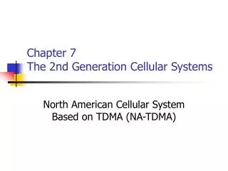
Fourth Generation Cellular Systems and Smart Antennas. Jack H. Winters. April 11, 2002 jack@jackwinters.com. Goal. Wireless communications, anywhere, in any form In any form: high-speed data (Internet) voice audio (music) video Anywhere: home buildings (office) pedestrian vehicles

E N D
Fourth Generation Cellular Systems and Smart Antennas Jack H. Winters April 11, 2002 jack@jackwinters.com
Goal • Wireless communications, anywhere, in any form • In any form: • high-speed data (Internet) • voice • audio (music) • video • Anywhere: • home • buildings (office) • pedestrian • vehicles • Secure wireless virtual office
OUTLINE • Current Systems • Current Trends • Strategy Proposal • Technical Issues
$/Cell $/Sub $ 500,000 $ 1000 $ 100 $ 500 $ 100 $ 10 802.11a 5.5GHz Unlicensed 802.11b 2.4GHz Unlicensed 3G Wireless ~ 2GHz Current Systems Peak Data Rate High performance/price 100 Mbps 10 Mbps 1 Mbps BlueTooth 2.4GHz 100 kbps High ubiquity and mobility Range 10 feet 100 feet 1 mile 10 miles Mobile Speed 60 mph 2 mph 10 mph 30 mph
Cellular Data • CDPD (US) < 10 kbps • GPRS = 30-40 kbps • EDGE = 80 kbps • WCDMA = 100 kbps (starting in Japan, but not for several years in US)
Barker Barker CCK CCK 1 ms 11 chips 727 ns 8 chips Key 802.11b Physical Layer Parameters: Data rate: • 1, 2, 5.5, 11 Mbps Modulation/Spreading: • Direct Sequence Spread Spectrum (DSSS) • DBPSK, DQPSK with 11-chip Barker code (1, 2 Mbps) (this mode stems from the original 802.11 standard) • 8-chip complementary code keying (CCK) (5.5, 11 Mbps) • optional: packet binary convolutional coding (PBCC), 64 state, rate 1/2 CC (BPSK 5.5 Mbps, QPSK 11 Mbps) Transmission modes:(dynamic rate shifting) Chip rate: 11 MHz Frequency band: Industrial, Scientific and Medical (ISM, unlicensed) 2.4 - 2.4835 GHz Bandwidth: 22 MHz - TDD Channel spacing: 5 MHz Number of channels: Total of 14 (but only the first 11 are used in the US), with only 3 nonoverlapping channels
3.2 ms FFT G 4 ms 52=48+4 tones 64 point FFT Key 802.11a Physical Layer Parameters: Data rate: 6, 9, 12, 18, 24, 36, 48, 54 Mbps Modulation: BPSK, QPSK, 16QAM, 64QAM Coding rate: 1/2, 2/3, 3/4 User data rates (Mbps): Subcarriers: 52 BPSK QPSK QAM16 QAM64 Pilot subcarriers: 4 R=1/2 6 12 24 FFT size: 64 R=2/3 48 4 ms Symbol duration: R=3/4 9 18 36 54 Guard interval: 800 ns Subcarrier spacing: 312.5 kHz Bandwidth: 16.56 MHz - TDD Channel spacing: 20 MHz Frequency band: Unlicensed national infrastructure (U-NII), 5.5 GHz Number of channels: Total of 12 in three blocks between 5 and 6 GHz :
Current Trends • Business WLANs dominate, but home usage growing faster (8 million WLANs sold last year) • Spontaneous appearance of neighborhood/residential access sites via consumer broadband wire-line connections • Public WLAN offerings for enterprise and home users when they are away from the office or home • Players: • Wayport: Covers over 450 hotels & 9 airports US, Canada, UK • Aggregators: • Deep Blue Wireless (hotels and coffee houses) • Joltage • Sputnik • hereUare • Boingo Wireless/
North America Bay Area Wireless User Group Equip2rip (Oahu, HI) Guerrilla.net (Boston) Pdx Personal Telco pdxwireless.org (Portland, Oregon) SBAY.ORG Wireless Network (San Francisco Bay Area) Seattle Wireless (Seattle) Seattle Wireless Internet Project SFLAN (San Francisco) Xlan (Seattle) Europe Consume (London, UK) Elektrosmog (Stockholm and Gothenburg) Wlan.org.uk (UK) Wireless France (France) Wireless MediaPoli (Helsinki) Australia Community 802.11b LANs Bay Area 802.11b Access Point Map
Possible Strategies • Broadband Residential Access • Provide 802.11b’s to selected cable modem customers or pole locations for universal wireless high-speed data coverage (1 mile radius) with access to other homes in neighborhood • Since cable modem is at 1.5 Mbps and 802.11b is at 11 Mbps, provide fiber to these selected homes or poles (economical for selected homes) • Broadband Business Access • Fiber to building access points (e.g., floors) • Extend to residences for virtual offices
WLAN Overlay for Broadband Cable Infrastructure HYBRID FIBER WIRELESS • Logical fit with cable infrastructure • Responds to ad-hoc and organized competition • Potential for higher data rate alternative to DOCSIS • Synergy with streaming digital media
Hybrid Fiber Wireless • Run fiber down streets (or to selected homes/businesses) to access points (1 mile apart) for universal coverage with one infrastructure) • Start with wireless data access (802.11b) • Extend range and migrate to: • Voice • Audio (music) • Video • Mobility • Higher data rates (54 Mbps - 802.11a and higher) • Virtual personal/office (remote workforce) environment
Technical Issues • Voice/Music streaming/Video streaming (802.11e) • Universal coverage (Internet roaming) • Range • Higher data rates • Capacity/Interference) • Key constraint: Stay within existing standards/standard evolution (enhance performance within standards and drive standards evolution)
Internet Roaming • Seamless handoffs between WLAN and WAN • high-performance when possible • ubiquity with reduced throughput • management/brokering of consolidated WLAN and WAN access • adaptive or performance-aware applications • I-mobile, CC/PP, location based • Nokia GPRS/802.11b PCMCIA card • NTT DoCoMo WLAN/WCDMA trial Cellular Wireless Internet Wireless LAN’s Home Enterprise Public
Technical Issues • Voice/Music streaming/Video streaming (802.11e) • Universal coverage (Internet roaming) • Range • Higher data rates • Capacity/Interference) • Key constraint: Stay within existing standards/standard evolution (enhance performance within standards and drive standards evolution)
$/Cell $/Sub $ 500,000 $ 1000 $ 100 $ 500 $ 100 $ 10 802.11a 5.5GHz Unlicensed 802.11b 2.4GHz Unlicensed 3G Wireless ~ 2GHz Wireless System Enhancements Peak Data Rate High performance/price 100 Mbps 10 Mbps Enhanced 1 Mbps BlueTooth 2.4GHz 100 kbps High ubiquity and mobility Range 10 feet 100 feet 1 mile 10 miles 60 mph Mobile Speed 2 mph 10 mph 30 mph
Enhancements • Smart Antennas (keeping within standards): • Range increase • Interference suppression • Capacity increase • Data rate increase using multiple transmit/receive antennas (MIMO) • Radio resource management techniques (using cellular techniques in WLANs): • Dynamic packet assignment • Power control • Adaptive coding/modulation/smart antennas • Modification of 802.11a/4G (a+) for one cellular/WLAN standard
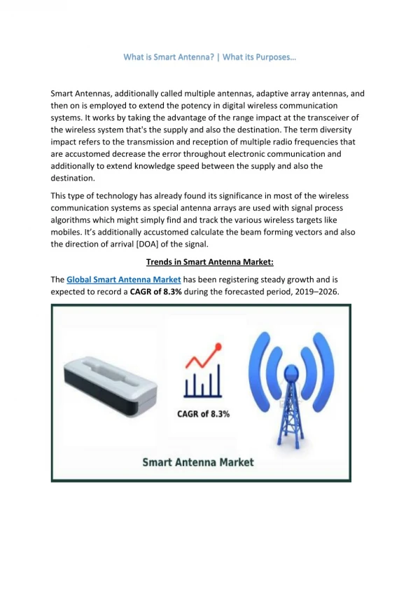
SIGNAL INTERFERENCE BEAMFORMER WEIGHTS INTERFERENCE Smart Antennas SIGNAL OUTPUT • Smart Antennas significantly improve performance: • Higher antenna gain with multipath mitigation (gain of M with M-fold diversity) Range extension • Interference suppression (suppress M-1 interferers) Quality and capacity improvement • With smart antennas at Tx/Rx MIMO capacity increase(M-fold)
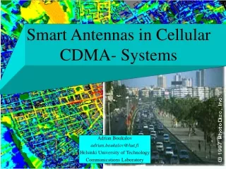
SIGNAL SIGNAL OUTPUT INTERFERENCE BEAMFORMER WEIGHTS BEAM SELECT SIGNAL SIGNAL OUTPUT BEAMFORMER INTERFERENCE Smart Antennas for Cellular • Key enhancement technique to increase system capacity, extend coverage, and improve user experience in cellular (IS-136) Uplink Adaptive Antenna Downlink Switched Beam Antenna In 1999, combining at base stations changed from MRC to MMSE for capacity increase
Multiple-Input Multiple-Output (MIMO) Radio • With M transmit and M receive antennas, can provide M independent channels, to increase data rate M-fold with no increase in total transmit power (with sufficient multipath) – only an increase in DSP • Indoors – up to 150-fold increase in theory • Outdoors – 8-12-fold increase typical • AT&T measurements show 4x bit rates & capacity increase in all mobile & indoor/outdoor environments (4 Tx and 4 Rx antennas) • 216 Mbps 802.11a (4X 54 Mbps) • 1.5 Mbps EDGE • WCDMA
11.3 ft Prototype Dual Antenna Handset Rooftop Base Station Antennas MIMO Channel Testing MobileTransmitters Test Bed Receivers with RooftopAntennas W1 Tx Rx • Perform timing recovery and symbol synchronization • Record 4x4 complex channel matrix • Evaluate capacity and channel correlation W2 Rx Tx Rx Tx W3 Terminal Antennas on a Laptop Rx Tx W4 Synchronous test sequences LO LO Mobile Transmitters
DIVERSITY TYPES • Spatial: Separation – only ¼ wavelength needed at terminal • Polarization: Dual polarization (doubles number of antennas in one location • Pattern: Allows even closer than ¼ wavelength • 4 or more antennas on a PCMCIA card • 16 on a handset • Even more on a laptop
MIMO Antennas Base Station Antennas • Antennas mounted on 60 foot tower on 5 story office building • Dual-polarized slant 45 1900 MHz sector antennas and fixed multibeam antenna with 4 - 30 beams Laptop Prototype • 4 patch antennas at 1900 MHz separated by 3 inches (/2 wavelengths) • Laptop prototype made of brass with adjustable PCB lid
MIMO Field Test Results • Measured capacity distribution is close to the ideal for 4 transmit and 4 receive antennas
Smart Antenna Smart Antenna AP AP Smart Antennas for WLANs Interference Smart Antennas can significantly improve the performance of WLANs • TDD operation (only need smart antenna at access point or terminal for performance improvement in both directions) • Interference suppression Improve system capacity and throughput • Supports aggressive frequency re-use for higher spectrum efficiency, robustness in the ISM band (microwave ovens, outdoor lights) • Higher antenna gain Extend range (outdoor coverage) • Multipath diversity gain Improve reliability • MIMO (multiple antennas at AP and laptop) Increase data rates
Smart Antennas • Adaptive MIMO • Adapt among: • antenna gain for range extension • interference suppression for capacity (with frequency reuse) • MIMO for data rate increase • With 4 antennas at access point and terminal, in 802.11a have the potential to provide up to 216 Mbps in 20 MHz bandwidth within the standard • In EDGE/GPRS, 4 antennas provide 4-fold data rate increase (to 1.5 Mbps in EDGE) • In WCDMA, BLAST techniques proposed by Lucent
Radio Resource Management • Use cellular radio resource management techniques in WLANs: Adaptive coding/modulation, dynamic packet assignment, power control • Not available on market • Current system administrators and users unaware of capacity/coverage issues • Performance statistics generated in current WLANs, but interpretation difficult • Techniques: • Use software on controller PC for multiple access points to analyze data and control system • Power control to permit cell ‘breathing’ (for traffic spikes) • Dynamic AP channel assignment • Combination of radio resource management and smart antennas yields greater gains than sum of gains
Cell Breathing in WLAN Systems AP AP AP AP AP AP AP AP AP AP AP AP AP AP • Measure traffic load for each access point • Shrink overloaded cell by reducing RF power • Expand others to cover abandoned areas
Cochannel interference High traffic load Adaptive Channel Assignment Initial Assignment After one iteration 2 1 3 3 2 3 3 1 2 3 1 2 2 2 3 2 3 1 • Assign channels to maximize capacity as traffic load changes
$/Cell $/Sub $ 500,000 $ 1000 $ 100 $ 500 $ 100 $ 10 802.11a 5.5GHz Unlicensed 802.11b 2.4GHz Unlicensed 3G Wireless ~ 2GHz Standards Evolution Peak Data Rate High performance/price 100 Mbps 10 Mbps 802.11a+ 1 Mbps BlueTooth 2.4GHz 100 kbps High ubiquity and mobility Range 10 feet 100 feet 1 mile 10 miles 60 mph Mobile Speed 2 mph 10 mph 30 mph
3.2 ms FFT G 4 ms 52=48+4 tones 64 point FFT Issues for 802.11a: Data rate: 6, 9, 12, 18, 24, 36, 48, 54 Mbps Modulation: BPSK, QPSK, 16QAM, 64QAM Coding rate: 1/2, 2/3, 3/4 Subcarriers: 52 - insufficient for high data rates in wide area Pilots subcarriers: 4 - insufficient if number of subcarriers increased FFT size: 64 - too small for number of carriers in crowded spectrum 4 ms - too short for efficient wide area operation Symbol duration: Guard interval: 800 ns - too short for wide area operation Subcarrier spacing: 312.5 kHz - too large for narrow channels Bandwidth: 16.56 MHz - too large for spectrum available Channel spacing: 20 MHz Carrier accuracy: 20 ppm - leads to too much carrier error Carrier error @5.8GHz: 114 kHz - too much for narrower channel spacing, even at 1.9 GHz
User data rates (Mbps): BPSK QPSK QAM16 QAM64 R=1/2 1.66 3.33 6.66 R=2/3 13.33 R=3/4 2.5 5 10 15 204.8 ms FFT G 230.4 ms 832=768+64 tones 2048 point FFT Changes for high-mobility operation: Data rate: 1.66, 2.5, 3.33, 5, 6.66, 10, 13.33, 15 Mbps Modulation: BPSK, QPSK, 16QAM, 64QAM Coding rate: 1/2, 2/3, 3/4 subcarriers: 832 = 52*16 Pilot subcarriers: 64 = 4*16 FFT size: 2048 = 64*32 230.4 ms = 3.2*64 + .8*32 Symbol duration: 25.6 ms = .8*32 Guard interval: Subcarrier spacing: 4.833 kHz = 312.5/64 Bandwidth: ~5 MHz » 16.56/4 Channel spacing: 5 MHz » 20/4 Carrier accuracy: .5 ppm for 5 GHz, 1 ppm for 2.4 GHz Carrier error @5.8GHz: 2.9 kHz, 1.9 kHz @ 1.9 GHz
OFDM tradeoffs DVB-T 2k mode 802.11a 4G Data rate 6, 9, 12, 18, 24, 36, 48, 54 Mb/s 2.56-8.96 Mb/s 4.98-31.67 Mb/s Tone modulation BPSK, QPSK, 16QAM, 64QAM QPSK, “16QAM,” “64QAM” QPSK,16QAM Coding rate [1/2, 2/3, 3/4, 5/6, 7/8] + RS(204,88) 1/2, 2/3, 3/4 1/2, 2/3, 3/4, 7/8 Nt 52 640 1705 4 ms 200 ms 231-280 ms tB 40 ms 7-56 ms tB-tF 800 ns ft 312.5 kHz 6.25 kHz 4.464 kHz fB 16.56 MHz 4 MHz 7.6 MHz fop ~5 GHz ~2 GHz ~500 MHz
Conclusions • We evolving toward our goal of universal high-speed wireless access, but technical challenges remain • These challenges can be overcome by the use of: • Smart antennas to reduce interference, extend range, increasedata rate, and improve quality, without standards changes • Radio resource management techniques, in combination with smart antennas – further enhanced by a standards evolution to 4G