UDP—User Datagram Protocol
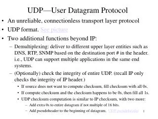
UDP—User Datagram Protocol. An unreliable, connectionless transport layer protocol UDP format. See picture Two additional functions beyond IP:


UDP—User Datagram Protocol
E N D
Presentation Transcript
UDP—User Datagram Protocol • An unreliable, connectionless transport layer protocol • UDP format. See picture • Two additional functions beyond IP: • Demultiplexing: deliver to different upper layer entities such as DNS, RTP, SNMP based on the destination port # in the header. i.e., UDP can support multiple applications in the same end systems. • (Optionally) check the integrity of entire UDP. (recall IP only checks the integrity of IP header.) • If source does not want to compute checksum, fill checksum with all 0s. • If compute checksum and the checksum happens to be 0s, then fill all 1s. • UDP checksum computation is similar to IP checksum, with two more: • Add extra 0s to entire datagram if not multiple of 16 bits. • Add pseudoheader to the beginning of datagram. UDP pseudoheader
Back to UDP—User Datagram Protocol UDP datagram 0 16 31 Source Port Destination Port UDP Length UDP Checksum Data Figure 8.16
Back to UDP—User Datagram Protocol UDP pseudoheader 0 8 16 31 Source IP Address Destination IP Address 0 0 0 0 0 0 0 0 Protocol = 17 UDP Length 1.Pseudoheader is to ensure that the datagram has indeed reached the correct destination host and port. 2. The padding of 0s and pseudoheader is only for the computation of checksum and not be transmitted. Figure 8.17
TCP—transmission control protocol • TCP functionality • Provides connection-oriented, reliable, in-sequence, byte-stream service • Provides a logical full-duplex (two way) connection • Provides flow-control by advertised window. • Provides congestion control by congestion window. • Support multiple applications in the same end systems. • TCP establishes connection by setting up variables that are used in two peer TCP entities. Most important variables are initial sequence numbers. • TCP uses Selective Repeat ARQ. • TCP terminates each direction of connection independently, allowing data to continue flowing in one direction after closing the other direction. • TCP does not keep messages boundaries and treats data as byte stream. e.g, when source sends out two chunks of data with length 400 and 600 bytes, the receiver may receive data in chunks of 300, 400, and 300 bytes, or 100 and 900 bytes.
TCP operations • TCP delivers byte stream.See picture • TCP deals with old packets from old connections by several methods. See picture • TCP uses sliding-window to implement reliable transfer of byte stream. See picture • TCP uses advertised window for flow control. • Adaptive timer: • tout = tRTT+4dRTT , • tRTT(new) = tRTT(old) +(1-)n , dRTT(new)=dRTT(old) + (1-)(n-tRTT) • Wheren is the time from transmitting a segment until receiving its ACK. , are in 0 to 1 with being 7/8 and being ¼ typically. tRTT ismean round-trip-time, dRTT is average of deviation. • TCP uses congestion window for congestion control. See picture
TCP byte stream Application Application byte stream byte stream segments Transmitter Receiver Send buffer Receive buffer ACKs Figure 8.18
Back to TCP operations An old segment could not be distinguished from current ones Host A Host B SYN, Seq_no = n SYN, Seq_no = n, ACK, Ack_no = n+1 Seq_no = n+1, ACK, Ack_no = n+1 Delayed segment with Seq_no = n+2 will be accepted Question: How does TCP prevent old packets of old connections? • Using long (32 bit) sequence number • Random initial sequence number -- set a timer at the end of a connection to clear all lost packets from this connection. • As a result, that an old packet from an old connection conflicts with packets in current connection is very low!! Figure 8.23
TCP uses Selective-Repeat ARQ Receiver Back to TCP operations Transmitter Receive Window Send Window Rlast+WR+1 Rlast Slast+WS-1 … … … ... ... ... Octets transmitted and ACKed Rnext Rnew Slast+WA-1 Slast Srecent Advertised window Rlast highest-numbered octet not yet read by the application Rnext next expected octet Rnew highest numbered octet received correctly Rlast+WR-1 highest-numbered octet that can be accommodated in receive buffer Slast oldest unacknowledged octet Srecent highest-numbered transmitted octet Slast+WA-1 highest-numbered octet that can be transmitted Slast+WS-1 highest-numbered octet that can be accepted from the application Note: 1.Rnew highest bytes received correctly, which are out-of sequence bytes. • 2. Advertised window WA: Srecent – Slast WA =WR – (Rnew – Rlast) Figure 8.19
Back to TCP operations Dynamics of TCP congestion window Congestion occurs Congestion 20 avoidance 15 Congestion window Threshold 10 Slow start 5 0 Round-trip times Figure 7.63
TCP protocol • TCP segment See Segment format • TCP pseudoheader. See pseudoheader • TCP connection establishment. See establishment • Client-server application See socket • TCP Data transfer • Sliding window with window sliding on byte basis • Flow control and piggybacking See flow control • TCP connection termination • After receiving ACK for previous data, but no more data to send, the TCP will terminate the connection in its direction by issuing an FIN segment. Graceful termination • TCP state transition diagram
TCP segment format Back to TCP protocol 0 4 10 16 24 31 Source Port Destination Port Sequence Number Acknowledgement Number U A P R S F Header R C S S Y I Reserved (Advertised) Window Size Length G K H T N N Checksum Urgent Pointer Options Padding Data 1.SYN:request to set a connection. 2. RST: tell the receiver to abort the connection. 3. FIN: tell receiver this is the final segment, no more data, i.e, close the connection in this direction. 4. ACK: tell the receiver (or sender) that the value is the field of acknowledgment number is valid. 5. PSH: tell the receiving TCP entity to pass the data to the application immediately. 6. URG: tell the receiver that the Urgent Pointer is valid. Urgent Pointer: this pointer added to the sequence number points to the last byte of the “Urgent Data”, (the data that needs immediately delivery). Figure 8.20
Back to TCP protocol TCP pseudoheader 0 8 16 31 Source IP Address Destination IP Address 0 0 0 0 0 0 0 0 Protocol = 6 TCP Segment Length The padding of 0s and pseudoheader is only used in computation of checksum but not be transmitted, as in UDP checksum. Figure 8.21
Back to TCP protocol Host A Host B • Random initial SN • Initial SNs in two • directions are different • 3. Initial SNs for two • connections are different. • 4. It should be clear here that • what setting up connection • means: • both A and B know that • they will exchange data, • and go into ready state to • send and receive data. • Most important is that • they agree upon the • initial SNs. SYN, Seq_no = x SYN, Seq_no = y, ACK, Ack_no = x+1 Seq_no = x+1, ACK, Ack_no = y+1 Three-way handshake to set up connection Figure 8.22
Back to TCP protocol Host B (Server) Host A (Client) socket bind listen accept (blocks) socket connect (blocks) SYN, Seq_no = x SYN, Seq_no = y, ACK, Ack_no = x+1 connect returns Seq_no = x+1, ACK, Ack_no = y+1 write read (blocks) accept returns read (blocks) request message read returns write read (blocks) reply message read returns Figure 8.24
Back to TCP protocol TCP window flow control Host A Host B t0 Seq_no = 1, Ack_no = 2000, Win = 2048, No Data t1 Seq_no = 2000, Ack_no = 1, Win = 1024, Data = 2000-3023 t2 Seq_no = 3024, Ack_no = 1, Win = 1024, Data = 3024-4047 t3 Seq_no = 1, Ack_no = 4048, Win = 512, Data = 1-128 t4 Seq_no = 4048, Ack_no = 129, Win = 1024, Data = 4048-4559 Figure 8.25
TCP graceful termination Back to TCP protocol Host A Host B Question: is termination easier than establishment? Or to say, is it possible that a connection is closed when both of two parties confirm with each other? FIN, seq = 5086 ACK = 5087 Data (150 bytes), seq. = 303, ACK = 5087 ACK = 453 No, Saying goodbye is hard to do. Famous blue-red armies problem. FIN, seq. =453, ACK = 5087 ACK = 454 Figure 8.27
Back to TCP protocol Thick lines: normal client states Dashed lines: normal server states CLOSED passive open, create TCB applic.close active open,create TCB send SYN LISTEN receive SYN, send SYN, ACK receive RST send SYN applic. close or timeout, delete TCB SYN_SENT SYN_RCVD receive SYN, send ACK receiveACK receive SYN, ACK, send ACK applic. close, send FIN ESTABLISHED receive FIN, send ACK applic. close, send FIN CLOSE_WAIT receive FIN send ACK applic. close send FIN CLOSING FIN_WAIT_1 receive ACK LAST_ACK receive ACK receive ACK receive FIN, ACK send ACK receive FIN send ACK 2MSL timeout delete TCB FIN_WAIT_2 TIME_WAIT Figure 8.28
Sequence number wraparound and timestamps • Original TCP specification for MSL (Maximum Segment Lifetime) is 2 minutes. • How long will it take to wrap around 32 bit sequence number when 232=4,294,967,296 bytes have been sent (maximum window size=231) • T-1 line, (2328)/(1.544 106) = 6 hours • T-3 line, (2328)/(45 106) = 12 minutes • OC-48 line, (2328)/(2.4 109) = 14 seconds !!! • When sequence number wrap around, the wraparounded sequence number will confuse with previous sequence number. • Solution: optional timestamp field (32 bits) in TCP header, thus, 232232=264 is big enough right now.
Internet routing protocols • Autonomous system (AS) • A set of routers or networks technically administrated by a single organization. • No restriction that an AS must run a single routing protocol • Only requirement is that from outside, an AS presents a consistent picture of which ASs are reachable through it. • Three types of ASs: • Stub AS: has only a single connection to outside. • Multihomed AS: has multiple connections to outside, but refuses to carry out transit traffic • Transit AS: multiple connections to outside and carry transit traffic. • ASs need to be assigned globally unique AS number (ASN)
Classification of Internet routing protocols • IGP (Interior Gateway Protocol): • For routers to communicate within an AS and relies on IP address to construct paths. • Provides a map of a county dealing with how to reach each building. • RIP (Routing Information Protocol): distance vector • OSPF (Open Shortest Path First): link state • EGP (Exterior Gateway Protocol): • For routers to communicate among different ASs and relies on AS numbers to construct AS paths. • Provides a map of a country, connecting each county. • BGP (Border Gateway Protocol): (distance) path vector
RIP—Routing Information Protocol • Distance vector • On top of UDP with port #520 • Metric is number of hops • Maximum number of hops is 15, 16 stands for infinity • Using split-horizon with poisoned reverse. • May speed up convergence by triggered updates. • Routers exchange distance vector every 30 seconds • If a router does not receive distance vector from its neighbor X within 180 seconds, the link to X is considered broken and the router sets the cost to X is 16 (infinity). • RIP-2 contains more information: subnet mask, next hop, routing domain, authentication, CIDR
0 8 16 31 Command Version Zero Address Family Identifier Zero IP Address Zero Zero Metric . . . RIP message format • Command: 1: request other routers to send routing information • 2: a response containing its routing information 2. Version: 1 or 2 3. Up to 25 routing information message 3.1 Family identifier: only 2 for IP address 3.2 IP address: can be a host address or a network address 3.3 Metric: 1—15. 16 indicates infinity Problems of RIP: not scalable, slow convergence, counting-to-infinity, therefore replaced By OSPF in 1979. Figure 8.32
Open Shortest Path First • RFC 2328 (v2) • Fixes some of the deficiencies in RIP • Enables each router to learn complete network topology • Each router monitors the link state to each neighbor and floods the link-state information to other routers • Each router builds an identical link-state database • Allows router to build shortest path tree with router as root • OSPF typically converges faster than RIP when there is a failure in the network
OSPF Features • Multiple routes to a given destination, one per type of service • Support for variable-length subnetting by including the subnet mask in the routing message • More flexible link cost which can range from 1 to 65,535 • Distribution of traffic over multiple paths of equal cost • Authentication to ensure routers exchange information with trusted neighbors • Uses notion of area to partition sites into subsets • Support host-specific routes as well as net-specific routes • Designated router to minimize table maintenance overhead
Flooding • Used in OSPF to distribute link state (LS) information • Forward incoming packet to all ports except where packet came in • Packet eventually reaches destination as long as there is a path between the source and destination • Generates exponential number of packet transmissions • Approaches to limit # of transmissions: • Use a TTL at each packet; won’t flood if TTL is reached • Each router adds its identifier to header of packet before it floods the packet; won’t flood if its identifier is detected • Each packet from a given source is identified with a unique sequence number; won’t flood if sequence number is same
10.5.1.2 10.5.1.4 10.5.1.1 10.5.1.6 10.5.1.3 10.5.1.5 Example OSPF Topology At steady state: • All routers have same LS database • Know how many routers in network • Interfaces & links between routers • Cost of each link • Occasional Hello messages (10 sec) & LS updates sent (30 min)
OSPF Network • To improve scalability, AS may be partitioned into areas • Area is identified by 32-bit Area ID • Router in area only knows complete topology inside area & limits the flooding of link-state information to area • Area border routers summarize info from other areas • Each area must be connected to backbone area (0.0.0.0) • Distributes routing info between areas • Internal router has all links to nets within the same area • Area border router has links to more than one area • backbone router has links connected to the backbone • Autonomous system boundary (ASB) router has links to another autonomous system.
OSPF Areas To another AS N1 R1 N5 N4 N2 R3 R6 R7 R2 N6 R4 R5 N3 Area 0.0.0.2 Area 0.0.0.0 Area 0.0.0.1 R8 ASB: 4 ABR: 3, 6, and 8 IR: 1,2,7 BBR: 3,4,5,6,8 N7 R = router N = network Area 0.0.0.3
Neighbor, Adjacent & Designated Routers • Neighbor routers: two routers that have interfaces to a common network • Neighbors are discovered dynamically by Hello protocol • Each neighbor of a router described by a state • down, attempt, init, 2-way, Ex-Start, Exchange, Loading, Full • Multiaccess networks: a set of routers that can communicate directly with each other. • Designated router in multiaccess networks: the router responsible for routing information exchange on behalf of the entire multiaccess network. • Adjacent router: neighbor routers become adjacent when they synchronize topology databases by exchange of link state information. • Neighbors on point-to-point links become adjacent • Routers on multiaccess nets become adjacent only to designated & backup designated routers • Reduces size of topological database & routing traffic. • The purpose of adjacent relation is that OSPF only exchange (flood) routing information among adjacent routers to reduce the routing information exchange.
Designated Routers • Reduces number of adjacencies • Elected by each multiaccess network after neighbor discovery by hello protocol • Election based on priority & id fields • Generates link advertisements that list routers attached to a multi-access network • Forms adjacencies with routers on multi-access network • Backup prepared to take over if designated router fails
Link State Advertisements • Link state info exchanged by adjacent routers to allow • area topology databases to be maintained • inter-area & inter-AS routes to be advertised • Router link ad: generated by all OSPF routers • state of router links within area; flooded within area only • Net link ad: generated by the designated router • lists routers connected to net: flooded within area only • Summary link ad: generated by area border routers • 1. routes to dest in other areas; 2. routes to ASB routers • AS external link ad: generated by ASB routers • describes routes to destinations outside the OSPF net • flooded in all areas in the OSPF net
OSPF Protocol • OSPF packets transmitted directly on IP datagrams; Protocol ID 89 • TOS 0, IP precedence field set to internetwork control to get precedence over normal traffic • OSPF packets sent to multicast address 224.0.0.5 (allSPFRouters on pt-2-pt and broadcast nets) • OSPF packets sent on specific IP addresses on non-broadcast nets • Five OSPF packet types: • Hello • Database description • Link state request; Link state update; Link state ack
Type: Hello, Database description, Link state request, Link state update, Link state acknowledgements 0 8 16 31 Version Type Packet length Router ID Area ID OSPF common header Checksum Authentication type Authentication Authentication OSPF packet body Data OSPF Header
OSPF Stages • Discover neighbors by sending Hello packets (every 10 sec) and designated router elected in multiaccess networks • Adjacencies are established & link state databases are synchronized • Link state information is propagated & routing tables are calculated We elaborate on OSPF stages in following
0 16 24 31 Network mask Hello interval Options Priority Dead interval Designated router Backup designated router Neighbor 1 . . . Neighbor n Stage 1: OSPF Hello Packet • Send Hello packets to establish & maintain neighbor relationship • Hello interval: number of seconds between Hello packets • Priority: used to elect designated router & backup • Dead interval: # sec before declaring a non-responding neighbor down. • Neighbor: the Router ID of each neighbor from whom Hello packets have recently been received
Stage 2: OSPF Database Description • Once neighbor routers become adjacent, they exchange database description packets to synchronize their link-state databases. • Init bit 1 if pkt is first in sequence of database description packets • More bit 1 if there are more database description packets to follow • Master/Slave bit indicates that the router is the master. • Link state ad (LSA) header describes state of router or network; contains info to uniquely identify entry in LSA (type, ID, and advertising router). • Can have multiple LSA headers
LS type: Router LSAs generated by all OSPF routers; Network LSAs generated by designated routers; Summary LSAs by area border routers; AS-external LSAs by ASBRs LS id: identifies piece of routing domain being described by LSA LS Seq. Number: numbers LSAs to detect old/duplicate LSAs LS checksum: covers contents of LSA except link state age 0 16 24 31 Link-state age Options Link-state type Link-state ID Advertising router Link-state sequence number Link-state checksum Length LSA Header
Database Synchronization • LS Database (LSDB): collection of the Link State Advertisements (LSAs) accepted at a node. • This is the “map” for Dijkstra algorithm • When the connection between two neighbors comes up, the routers must wait for their LSDBs to be synchronized. • Else routing loops and black holes due to inconsistency • OSPF technique: • Source sends only LSA headers, then • Neighbor requests LSAs that are more recent • Those LSAs are sent over • After sync, the neighbors are said to be “fully adjacent”
0 31 Link-state type Link-state ID Advertising router . . . Stage 3: OSPF Link State Request • Router sends a LS request packet to neighbor to update part of its link-state database • Each LSA request is specified by the link state type, link state ID, and the advertising router.
In response to LS request or trigger, router will send new LS info using the LS update message Contents are composed of link state advertisements (LSAs) LS update message is acknowledged using LS ack pkt to ensure that the flooding algorithm is reliable; Link state acknowledgement packets consist of a list of LSA headers. 0 31 Number of LSAs LSA 1 . . . LSA n OSPF Link State Update
Border Gateway Protocol • InterAS routing protocol • (Distance) Path-vector protocol: not keep cost (distance) to each destination, but keep exact AS path to the destination • In order to exchange routing information, the TCP connection was established • TCP connection is 179. • Routing decision is mainly based on policies, not the reachability • Initially complete routing information are exchanged, then incremental updates are sent.
AS2 AS1 AS6 AS5 AS3 AS4 AS7 Border Gateway Protocol v4 • BGP (RFC 1771) an EGP routing protocol to exchange network reachability information among BGP routers (also called BGP speakers) • Network reachability info contains sequence of ASs that packets traverse to reach a destination network • Info exchanged between BGP speakers allows a router to construct a graph of AS connectivity • Routing loops can be pruned • Routing policy at AS level can be applied
BGP Features • BGP is path vector protocol: advertises sequence of AS numbers to the destination network • Path vector info used to prevent routing loops • BGP enforces policy through selection of different paths to a destination and by control of redistribution of routing information • Uses CIDR to support aggregation & reduction of routing information
BGP Speaker & AS Relationship • BGP speaker: a router running BGP • Peers or neighbors: two speakers exchanging information on a connection • BGP peers use TCP (port 179) to exchange messages • Initially, BGP peers exchange entire BGP routing table • Incremental updates sent subsequently • Reduces bandwidth usage and processing overhead • Keepalive messages sent periodically (30 seconds) • Internal BGP (iBPG) between BGP routers in same AS • External BGP (eBGP) connections across AS borders
R eBGP eBGP R iBGP R R iBGP iBGP iBGP iBGP R R iBGP eBGP eBGP R R iBGP & eBGP • eBGP to exchange reachability information in different AS’s • eBGP peers directly connected • iBGP to ensure net reachability info is consistent among the BGP speakers in the same AS • usually not directly connected • iBGP speakers exchange info learned from other iBGP speakers, and thus fully meshed
Path Selection • Each BGP speaker • Evaluates paths to a destination from an AS border router • Selects the best that complies with policies • Advertises that route to all BGP neighbors • BGP assigns a preference order to each path & selects path with highest value; BGP does not keep a cost metric to any path • When multiple paths to a destination exist, BGP maintains all of the paths, but only advertises the one with highest preference value
BGP Policy • Examples of policy: • Never use AS X • Never use AS X to get to a destination in AS Y • Never use AS X and AS Y in the same path • Import policies to accept, deny, or set preferences on route advertisements from neighbors • Export policies to determine which routes should be advertised to which neighbors • A route is advertised only if AS is willing to carry traffic on that route
BGP Protocol • Opening & confirming of a BGP connection with a neighbor router • Maintaining the BGP connection • Sending reachability information • Notification of error conditions
0 8 16 24 31 Marker Length Type: OPEN Version My autonomous system Hold time BGP identifier Optional parameters length Optional parameters Optional parameters BGP Open Message • Marker: authenticates incoming BGP messages or detects loss of synchronization between a pair of BGP peers. • Hold time: to propose number of seconds between transmission of successive KEEPALIVE messages • BGP ID: identifies sending BGP router; value is determined by one of the IP local interface addresses of the BGP router