Download
1 / 50
500 likes | 518 Vues
This unit explores the calculation of pump discharge pressure, ways to reduce friction loss, and the causes and effects of pump cavitation. It also covers the use of ejectors during pumping operations and how hydraulics affect drafting procedures. Learn through discussion, demonstration, and friction loss calculations using calculators.

E N D
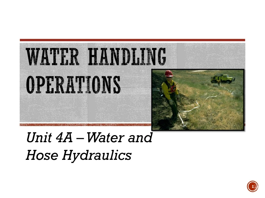
Water Handling Operations Unit 4A – Water and Hose Hydraulics
Identify… The elements that should be considered when calculating pump discharge pressure. Ways to reduce friction loss. Perform… Friction loss calculations using Friction loss calculators Principles of Hydraulics – Rule of 5s Describe, Discuss, and/or Demonstrate… The causes and effects of pump cavitation and the corrective actions the ENOP must take if cavitation occurs. Ejector use during pumping operations. How hydraulics affect drafting procedures used to refill an engine. Objectives
Pump Discharge Pressure (PDP) • The amount of pressure in pounds per square inch (PSI) as measured at the pump discharge.
Nozzle Pressure - (NP) • Pressure that must be delivered to the nozzle to produce an effective stream. • Optimum operating pressures: • Straight stream and Forester nozzles is 50 PSI • Variable pattern or fog nozzle is 100 PSI
Head Pressure - (H) • Head pressure is the weight of a given height (depth) of water column at its base. • Also known as lift, back pressure, gravity/elevation loss or gain • Measured in terms of feet of water • One foot of water exerts a pressure of .5 PSI at the base of a column of water. OR • Two feet of water exerts a pressure of 1 PSI at the base of a column of water.
Friction Loss - (FL) • Pressure loss caused by the turbulent movement of water or solution against the interior surface of fire hose, pipe, or fittings. • Normally measured in pressure loss (PSI) per 100’ length of hose or pipe.
Appliances - (A) • Items (gated wyes, inline tees, and check valves) that connect or interconnect the hose and pump together to form a hose lay. • Appliances have an insignificant effect on friction loss calculations at flows used in wildland suppression and have been omitted from calculations in this lesson. • Friction loss for 1½” fittings at 50 GPM: • Wye valve: 0.46 PSI • Inline tee: 0.05 PSI • Inline tee w/valve 0.77 PSI
Friction Loss Calculations Overview
Why do we need to perform friction loss calculations? To gain an understanding of the capabilities and limitations of our equipment To identify unsafe and inefficient operations
References and Tools • Wildland Fire Hose Guide • Water Handling Equipment Guide • Incident Response Pocket Guide • Friction Loss Calculator • Principles of Hydraulics—“Rule of 5s”
Friction Loss Formula Pump Discharge Pressure (PDP) = Nozzle Pressure (NP) +/- Head (Elevation Gain or Loss) (H) + Friction Loss (FL) PDP = NP +/- H + FL
Considerations • Must know the flow, or gallons per minute (GPM) that each nozzle will discharge. • Simple hose lays • Always start at the nozzle and work towards the pump. • Progressive hose lays • Always start from the most distant nozzle and work towards the pump. • Always pump to the highest pump discharge pressure (PDP) required. • Gate down any laterals that require substantially less pressure.
Friction Loss Calculation Exercises Pre-course Work
Exercise 1Pre-course Work 20 GPM + NP = 50 Forester nozzle +/- H = 0 no elevation change + FL = 101½” hose @ 20 GPM (2 PSI/100’ or 10 PSI/500’) PDP = 60 PSI You are pumping a 1½” hose lay 500’ long with a 5/16” tip. What is the GPM? What is the PDP?
Exercise 2Pre-course Work 30 GPM You are pumping 600’ of 1½” hose 50’ above the pump with a ⅜” tip. • What is the GPM? • What is the PDP? + NP = 50Forester nozzle +/- H = +25 50’ of elevation gain (50 ÷ 2) + FL = 18 1½” hose @ 30 GPM (3 PSI/100’ or 18 PSI/600’) PDP = 93PSI
Exercise 3Pre-course Work 13 GPM 26 GPM 13 GPM + NP = 50Forester nozzle +/- H = 0 no elevation change + FL= 5 1” hose @ 13 GPM (5 PSI/100’) + FL= 91½” hose @ 26 GPM (3 PSI/100’ or 9 PSI/300’) PDP =64PSI You are pumping 300’ of 1½” hose through a wye to 2 sections of 1” hose, each 100’ long with ¼” tips (remember tips are 50 PSI). What are the GPMs? What is the PDP?
Exercise 4Pre-course Work 50 GPM + NP = 100variable flow nozzle +/- H = 0 no elevation change + FL= 15 1” hose @ 25 GPM(15 PSI/100’) + FL=3 1½” hose @ 25 GPM(3 PSI/100’) + FL = 135 1½” hose @ 50 GPM (9 PSI/100’ or 135 PSI/1,500’) PDP =253PSI You are pumping to a hose lay with the first lateral at 1,500’. You have another 100’ of 1½” hose to another lateral. Both laterals are flowing 25 GPMs out of variable flow nozzles. What are the GPMs? What is the PDP?
Friction Loss Calculation Exercises In-class
Exercise 5In-class 90 GPM 60 GPM + NP = 100variable flow nozzle +/- H = 0 no elevation change + FL= 23 1” hose @ 30 GPM (23 PSI/100’) + FL=3 1½” hose @ 30 GPM (3 PSI/100’) + FL=26 1½” hose @ 60 GPM (13 PSI/100’) + FL=28 1½” hose @ 90 GPM (28 PSI/100’) + FL = 42 1½” hose @ 90 GPM (7 PSI/100’) PDP =222PSI You have 600’ of 1½” parallel hose to a Siamese valve. Attached to the wye is 100’ of 1½-inch hose to another wye and the first lateral, another 200’ of 1½” hose to the second lateral, and another 100’ of 1½” hose to last lateral. Each lateral is 100’ of 1” hose with a variable flow nozzle flowing 30 GPM. Consider this flat ground. What are the GPMs? What is the PDP?
Exercise 6In-class 60 GPM + NP = 100variable flow nozzle +/- H = +30 60’ elevation gain (60 2) + FL= 23 1” hose @ 30 GPM (23 PSI/100’) + FL=6 1½” hose @ 30 GPM (3 PSI/100’) + FL=13 1½” hose @ 60 GPM (13 PSI/100’) + FL = 12 1½” hose w/Siamese valve @ 60 GPM (3 PSI/100’) PDP =184PSI You have 400’ of 1½” parallel hose to a Siamese valve. Attached to the Siamese is 100’ of 1½” hose to a wye and the first lateral, another 200’ of 1½” hose to the second lateral. Each lateral is 100’ of 1” hose with a variable flow nozzle flowing 30 GPM. There is a 60’ rise in elevation. What are the GPMs? What is the PDP?
Exercise 7In-class 50 GPM + NP = 100variable flow nozzle +/- H = -10 cumulative 20’ elevation drop (20 2) + FL= 15 1” hose @ 25 GPM (15 PSI/100’) + FL=31½” hose @ 25 GPM (3 PSI/100’) + FL=27 1½” hose @ 50 GPM (9 PSI/100’) + FL = 15 1½” hose w/2 Siamese valves @ 50 GPM (3 PSI/100’) PDP =150PSI You have 500’ of 1½” parallel hose to a Siamese valve with a 30’ drop in elevation. Attached to the Siamese valve is 300’ of 1½” hose to a wye and the first lateral has a gain of 10’ in elevation. There is another 100’ of 1½” hose to the second and last lateral. Each lateral is 100’ of 1” hose with a variable flow nozzle flowing 25 GPM. What is the PDP?
Friction Loss Calculations “Rule of 5S”
“Rule of 5s” Rule based on experience or practice rather than on scientific knowledge. Method of estimating that is practical though not precise.
Friction Loss“Rule of 5s” 1½” Hose < 60 GPM = 5 PSI/100’ 1½” Hose Siamese (all flows) = 5 PSI/100’ 1” Hose (all flows) = 10 PSI/100’ 1½” Hose ≥ 60 GPM = 15 PSI/100’
Exercise 1“Rule of 5s” 20 GPM + NP = 50 Forester nozzle +/- H = 0 no elevation change + FL = 251½” hose @ 20 GPM (5 PSI/100’ or 25 PSI/500’) PDP = 75 PSI You are pumping a 1½” hose lay 500’ long with a 5/16” tip. What is the GPM? What is the PDP?
Exercise 2“Rule of 5s” 30 GPM + NP = 50Forester nozzle +/- H = +25 50’ of elevation gain (50 ÷ 2) + FL = 30 1½” hose @ 30 GPM (5 PSI/100’ or 30 PSI/600’) PDP = 105PSI You are pumping 600’ of 1½” hose 50’ above the pump with a 3/8” tip. What is the GPM? What is the PDP?
Exercise 3“Rule of 5s” 30 GPM 15 GPM 15 GPM + NP = 50nozzle +/- H = 0 no elevation change + FL = 10 1” hose @ 13 GPM (10 PSI/100’) + FL= 151½” hose @ 26 GPM (5 PSI/100’ or 15 PSI/300’) PDP =75PSI You are pumping 300’ of 1½” hose through a wye to two sections of 1” hose, each 100’ long with ¼” tips (remember tips are 50 PSI). What are the GPMs? What is the PDP?
Exercise 4“Rule of 5s” 25 GPM 50 GPM 25 GPM You are pumping to a hose lay with the first lateral at 1,500’. You have another 100’ of 1½” hose to another lateral. Both laterals have variable flow nozzles. • What are the GPMs? • What is the PDP? + NP = 100variable flow nozzle +/- H = 0 no elevation change + FL= 10 1” hose @ 25 GPM (10 PSI/100’) + FL=5 1½” hose @ 25 GPM (5 PSI/100’) + FL = 75 1½” hose @ 50 GPM (5 PSI/100’ or 75 PSI/1,500’) PDP =190PSI
Exercise 5“Rule of 5s” 90 GPM 60 GPM You have 600’ of 1½” parallel hose to a Siamese valve. Attached to the wye is 100’ of 1½” hose to another wye and the first lateral, another 200’ of 1½” hose to the second lateral, and another 100’ of 1½” hose to last lateral. Each lateral is 100’ of 1” hose with a variable flow nozzle flowing 30 GPM. Consider this flat ground. • What are the GPMs? • What is the PDP? + NP = 100variable flow nozzle +/- H = 0 no elevation change + FL = 10 1” hose @ 30 GPM (10 PSI/100’) + FL = 51½” hose @ 30 GPM (5 PSI/100’) + FL = 30 1½” hose @ 60 GPM (13 PSI/100’) + FL = 15 1½” hose @ 90 GPM (15 PSI/100’) + FL = 30 1½” hose @ 90 GPM (30 PSI/100’) PDP =190PSI
Exercise 6“Rule of 5s” 60 GPM You have 400’ of 1½” parallel hose to a Siamese valve. Attached to the Siamese valve is 100’ of 1½” hose to a wye and the first lateral, another 200’ of 1½” hose to the second lateral. Each lateral is 100’ of 1” hose with a variable flow nozzle flowing 30 GPM. There is a 60’ rise in elevation. • What is the GPM? • What is the PDP? + NP = 100variable flow nozzle +/- H = +30 60’ elevation gain (60 2) + FL= 10 1” hose @ 30 GPM (10 PSI/100’) + FL=101½” hose @ 30 GPM (10 PSI/200’) + FL=15 1½” hose @ 60 GPM (15 PSI/100’) + FL = 20 1½” hose w/Siamese valve @ 60 GPM (20 PSI/100’) PDP =185PSI
Exercise 7“Rule of 5s” 50 GPM + NP = 100variable flow nozzle +/- H = -10 cumulative 20’ elevation drop (20 2) + FL= 10 1” hose @ 25 GPM (10 PSI/100’) + FL=5 1½” hose @ 25 GPM (5 PSI/100’) + FL=15 1½” hose @ 50 GPM (5 PSI/300’) + FL = 25 1½” hose w/2 Siamese valves @ 50 GPM (25 PSI/500’) PDP =145PSI You have 500’ of 1½” parallel hose to a Siamese valve with a 30’ drop in elevation. Attached to the Siamese valve is 300’ of 1½” hose to a wye and the first lateral has a gain of 10’ in elevation. There is another 100’ of 1½” hose to the second and last lateral. Each lateral is 100’ of 1” hose with a variable flow nozzle flowing 25 GPM. What is the GPM? What is the PDP?
Comparing Methods How do they compare?
Why are there differences? • Friction Loss Calculator • Derived from a mathematical equation • “Rule of 5s” • An estimation
NO! Are the differences significant enough . . .? The goal is to supply an adequate amount of water and pressure to the nozzle operator(s). We are making a “reasonable estimate” of friction loss. Calculations for either method is not exact. Both methods provide a starting point to meet the goal.
A Comparison Friction Loss Calculator “Rule of 5s” • Provides consistency and validation (the theory behind hydraulics). • Based on theories. • Provide quick solutions for fire situations. • Make fast and practical decisions during hose lay construction.
Reducing Friction Loss • Increase hose diameters where possible. • Lay parallel hose. • Calculate friction loss for one hose, then divide by 4. • Reduce pump discharge pressure • Less flow = less friction loss. • May notprovide GPMs required! • Reduce the nozzle tip size. • Reduces discharge flow. • Eliminate unnecessary plumbing parts.
Other considerations Pump Cavitation, Drafting, & Ejector Use
Pump Cavitation • Pump cavitation occurs when more water is being discharged from the pump than is being supplied to the pump. • This creates a low-pressure area within the eye of the pump that causes vapor bubbles to form and implode on the discharge side of the pump.
Effects of Cavitation • When water enters the low-pressure area at the eye of the impeller, water vaporizes, or boils more easily. • When vapor bubbles reach the pressure or discharge side of the pump, they implode, or forcefully collapse, resulting in an intense shock wave which creates dings and pits of the pump walls and impeller. • Damage is cumulative and progressive. • Excessive cavitation will eventually lead to impeller failure
Signs of Cavitation Pump RPMs suddenly increase due to a lack of water resistance on the impeller. Rattling, whining, or a sound like gravel flowing through the pump. Increase in pump RPMs without an increase in pump discharge pressure (PDP).
Corrective Actions • Increase the supply of water coming into the pump and/or decrease the volume going out from the pump. • Clean out the suction strainer. • Do not deadhead the pump for prolonged period. • Ensure that water is circulating through the plumbing. • If the pump is not staffed, the low-pressure shutoff switch must be in the down position.
Drafting General Facts • Atmospheric pressure is approximately 15 pounds per inch (PSI) at sea level. • An excellent pump can pull water 24’ at sea level. • Atmospheric pressure decreases .5 PSI for each 1,000 foot increase in elevation. • *If you remember, head pressure equals .5 PSI/foot, therefore … • Each 1,000’ increase in elevation results in a loss of about 1’ of draft power. • Locating a pump as close to the water source as possible and reducing the vertical distance a pump must draft will increase its pumping ability.
Drafting Using EnginePump Setup • Locate a water source with adequate water supply. • Always obtain permission from the land owner before using a private water source. • Source site should allow for good ingress and egress. • Source site should free of floating debris. • All fittings and hoses on the suction side should be free of air leaks.
Drafting Using EnginePump Setup • Foot valve should be completely submerged, free of debris, and properly functioning. • Obtain a prime by using the hand/electric primer on the engine or fill the draft hose with water manually. • Set the water pressure shutdown switch to the up (override) position. Leave the switch in this position for the entire drafting process.
Drafting Using EnginePump Setup • Set correct valve configuration. • Draft-to-tank • Draft-to-fire • Confirm pump is drafting water into the tank.
Ejector Use - Refill OperationsGeneral Information • Picks up between 50-150% additional flow of water. • Can lift water 80’ or more vertically. • Can move water 300’ or more horizontally. • Must have enough water in the tank to fill all hose used on intake and return line.
Ejector Setup • Connect a section of 1-inch hose to overboard discharge and the water inlet side of the ejector. • Attach a strainer foot valve to ejector suction port of the ejector. • Attach 1½” hose to discharge side of ejector. • Submerge ejector in water source.
Ejector Setup • Start pump and throttle up to desired output. • 100-150 PSI at ejector is adequate. • Keep kinks out of supply and return lines. • If the site is going to be used multiple times, then leave hardware in place for refill operations.
Identify… The elements that should be considered when calculating pump discharge pressure. Ways to reduce friction loss. Perform… Friction loss calculations using Friction loss calculators Principles of Hydraulics – “Rule of 5s” Describe, Discuss, and/or Demonstrate… The causes and effects of pump cavitation and the corrective actions the ENOP must take if cavitation occurs. Ejector use during pumping operations. How hydraulics affect drafting procedures used to refill an engine. Objectives