Download
1 / 75
750 likes | 902 Vues
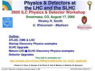
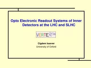
Opto Electronic Readout Systems of Inner Detectors at the LHC and SLHC Cigdem Issever University of Oxford. Outlook – Readout Systems at (S)LHC. SCT Barrel 3. 1. ATLAS 2. CMS 3. SLHC. Inner Tracker Barrel , L4+. TRT. Pixels. SCT. ATLAS Inner Detector. Performance | η | < 2.5

E N D
Opto Electronic Readout Systems of Inner Detectors at the LHC and SLHC Cigdem Issever University of Oxford
Outlook – Readout Systems at (S)LHC SCT Barrel 3 1. ATLAS 2. CMS 3.SLHC Inner Tracker Barrel , L4+ C. Issever
TRT Pixels SCT ATLAS Inner Detector • Performance • |η| < 2.5 • high pt tracks: • σ(1/pt,|η|<2) = 0.4 TeV-1 • σ(1/pt,|η|=2.5) = 1.2 TeV-1 • Impact parameter (high pt) • σr-φ< 20 m, σz< 100 m • ε ~ 95%, 90% in jets • Lifetime ~10 LHC years
ATLAS SCT Opto Readout System ~17500 links (SCT+pixel) Data L1, clock commands C. Issever
ATLAS SCT Optical Readout System • Readout of modules: • binary readout • Transfer data from 4088 modules @ 40Mbits/secto ReadOut Drivers (RODs). • Two links per module (redundancy) to the ROD • BC Clock & L1 Trigger & commands to the modules: • Transfer TTC data from RODs to modules @ 40Mbits/sec. • Biphase mark encoding (same fibre for clock and commands). • One link per module, in case of failure redundancy link to neighbouring module. C. Issever
ATLAS SCT Readout Summary • ATLAS SCT links built and do work. Used successfully for readout of barrels and End Caps. • Main concerns: • Breaking of Al LMTs during installation • ESD damage may have reduced the lifetime of the VCSELs. • Need to design simpler more modular systems for SLHC. • Very complicated system design: • 16 flavours of barrel opto-flex cables • 42 flavours of barrel harnesses • Large and non-modular system • Difficult to produce with high yield http://atlas.web.cern.ch/Atlas/GROUPS/INNER_DETECTOR/inner_detector.html C. Issever
CMS Tracker analogue optical link • Transmitter : 1310nm InGaAsP EEL • Fibres and connectors : Ge-doped SM fibre • Receivers : InGaAs 12-way p-i-n • plus analogue electronics : rad-hard deep sub-micron C. Issever
CMS Tracker Readout and Control Links Analogue Readout 50000 links @ 40MS/s 3 x ATLAS FED Detector Hybrid Tx Hybrid 96 Rx Hybrid processing MUX A buffering APV 4 DAQ 2:1 D amplifiers 12 12 C pipelines 128:1 MUX PLL Delay Timing DCU TTCRx FrontEnd AOH Digital Control 2000 links @40MHz TTC FEC Control 64 4 TTCRx CCU CCU 8 processing redundancy buffering CCU CCU Back-End, Controll room Front-End Radiation zone C. Issever
CMS’s Ansatz: COTS • Extensive use of Commercial Off-The-Shelf components (COTS) in CMS optical links • Benefit from latest industrial developments • cheaper • “reliable” tested devices • However COTS not made for CMS environment • no guarantees of long-life inside CMS • validation testing of COTS mandatory before integration into CMS C. Issever
CMS Readout Summary http://cern.ch/cms-tk-opto/ • CMS Tracker Optical links project • 50000 analogue + 1000 digital links • COTS components • Extensive validation testing of radiation hardness necessary • ionization damage (total dose) & SEU • displacement damage (total fluence), annealing, reliability • Accumulated knowledge of radiation damage effects • compensation built into optical link system • confidence of capacity to operate for 10 years inside CMS Tracker • If CMS would build it again: • simplify logistics, delegating even more to even fewer industries, • enforce common solutions and reduce the number of variants. • would also include hybrids and cables into the system design before freezing the components design. C. Issever
Performance of CMS/ATLAS Lasers CMS, EEL: no annealing shown, threshold shifts ~70% will anneal at low flux. Optical Readout and Control Systems for the CMS Tracker, J. Troska et al., IEEE 2002 ATLAS, VCSELs: annealed for 1 week, threshold shifts ~20% @ 1.5E+15n/cm2. Radiation hardness and lifetime studies of the VCSELs for the ATLAS SemiConductor Tracker, P.K. Teng et al., NIMA 497(2003)294
SLHC Inner Detector Readout SLHC: challenging radiation environment!! Schedule • Luminosity upgrade of LHC (SLHC) ~2015 • Start of construction ~ 2009/2010 • R&D for ID at SLHC is starting. • 100 Mrad Estimation based on IM. Gregor, Optical Links for ATLAS Pixel Detector, Thesis, WUB DIS 2001 - 03, 2001, Wuppertal C. Issever
SLHC Inner Detector Readout Challenges • 10 x more radiation • ≤ 10 x channels • Space and material constraints • 2 – 10 GBits/sec O(100) x faster • Very short time for R&D and construction Readout for the SLHC: high-speed, radhard and efficient to build C. Issever
SLHC : Early Questions to be Answered • Can some devices be reused (e.g. cable plants) • How much fluence can the current devices tolerate: • Lasers, PIN diodes • 0.25 micron technology, which no option for SLHC but gives an estimate for the radiation hardness of submicron technology. (i.e. GOL, QPLL-chip used by LHCb & CMS) • Fibres • Are there radhard COTS for the SLHC? • Test of custom-made devices. • What is the SEU cross section @ GBits/sec? Answers will determine which devices to use and where to place devices. C. Issever
SLHC: Light Output after Irradiation -- VCSELs VCSELs annealed for 21h – 35h ~70% of pre-irradiated VCSELs 50% Fatal failures C. Issever
SLHC: Fatal Failures -- VCSELs >5E+15 n/cm2 first fatal failures. Failures needs to be further investigated. Could be mechanical. C. Issever
SLHC: Fujikura SIMM(50/60/125) Fibre Gamma Irradiations Very good performance ≤1.33%/m loss C. Issever
SLHC: ATLAS & CMS • CMS • digital? under discussion • tracker into trigger 10GBits/sec • ATLAS • digital ? under discussion • ~1-2 GBits/sec • Same system is unlikely, but groups organized themselves to share as much as possible. • Develop same radiation procedures, • Share beam time, • Communicate! And use expertise of both experiments! • www.-pnp.physics.ox.ac.uk/~issever/Homepage/Opto/opto.html C. Issever
Summary • For LHC ATLAS and CMS have two different solutions for readout • SLHC much more challenging! Radiation, Time and Costs • For Future: Simpler and include hybrids and cables into the system design early on! • Even if CMS and ATLAS end up with two different solutions, Collaboration is needed to gain from extensive expertise on both sides. C. Issever
Backup Slides C. Issever
The next slides are from A. Weidberg’s LECC 2005 talk: “The Production of the SCT Optical Links”
Module Connector Location for opto-package Connector to Power Tape Bare Opto-flex C. Issever
Opto-flex on barrel Al Power tapes Module Connector Cover for ASICs and VCSEL/PIN Fibres in furcation tubing C. Issever
Harnesses on Barrel 3 1 of 384 flex circuits C. Issever
Barrel 3 with harness & Cooling Loops C. Issever
EC Opto and Power • Similar components but more modular system (possible because of clearances). Separate • Fibre harnesses with opto-packages • Power tapes C. Issever
Ribbon fibre opto-packages on plug-in PCB Splice protector Forward Fibre Harness Assembly Infineon and MT 12 way fibre ribbon connector Fibres in furcation tubing and Al foil for ribbon Opto-package on PCB with connector C. Issever
End Cap Flex Circuits CuKapton for HV and control signals CCA twisted pair for high current (DC power) Stiffener C. Issever
Opto-package Fibres in furcation tubing Dummy module Cooling pipe C. Issever
Modulewith ASICs silicon Flex Circuits Redundancy links Opto-package with fibres
Off-Detector Opto-Electronics • Based on novel packaging for 12 way VCSEL and PIN arrays. • BPM-12 ASIC to encode data and drive VCSELs for TTC data modules. • DRX-12 ASIC to discriminate optical data from modules. C. Issever
Opto-Array Sub Assembly C. Issever
RX/TX Plugins M-L. Chu et al. NIM A 530 (2004) 293-310. 12 way PIN array 12 way VCSEL array C. Issever
VCSEL performance Cut BER < 10-12 for data and TTC links. • Links used successfully in readout of barrels and End Caps. • > 99.7% (99.7%) working channels for Barrels (EC-C) LECC 2005
Problems • Complexity and yield • Cracks on kapton flex circuits • (Light leakage) • ESD • Resonant bond wire vibrations C. Issever
Complexity • Very complicated system design: • 16 flavours of barrel opto-flex cables • 42 flavours of barrel harnesses • Large and non-modular system • Difficult to produce with high yield • Mistake in geometry opto-flex cables for barrels 4 and 6 had the module connectors out by 2.8 mm couldn’t connect to the modules. • tPCB added to solve problem. • Conclusion: much simpler design would have achieved same physics performance but would have been much easier to build. tPCB (bricolage) C. Issever
Cracks Barrel kapton flexes • Layout of opto-flexes not optimised because there were too many flavours to design! • Added ceramic stiffeners behind connectors. Crack! LECC 2005
Cracks End Cap Flex Circuits • Cu/kapton alone and Al t.p. alone robust. • Problem is Al much more rigid than Cu/kapton cracking during bending. Kapton tape over t.p. and flex circuit.
Cracks in Al LMTs • Al/kapton LMTs used to bring in power/control lines to modules. • Al is ~ 4 times better than Cu for X0/r. • Al/kapton was reasonably robust • Cracks found on exposed Ni plated regions ( photos). Cover layer Ni ~ 5 mm PbSn Solder ~ 10 mm Kapton 50 mm Al 50 mm Glue 25 mm
500 mm Cracks appear to form on grain boundaries C. Issever
Cracks on Al LMTs: Conclusion • Believe that cracks are due to hydrogen released during Ni plating leading to hydrogen embrittlement of Al. • Rate of cracks on barrel harnesses: ~ 1%. • Much higher rate of cracks found on End Cap LMT harnesses (probably because there was insufficient room for mechanical protection). • New Cu/Espanex LMTs being produced for the End Caps. C. Issever
ESD Deaths • ESD and DORIC4A ASIC • ESD and VCSELs • One strike and you are out C. Issever
ESD On DORIC4A ASIC Cause of ESD identified as bad handling procedure procedures improved and all suspect chips removed. Damagedtracks C. Issever
VCSEL ESD Failures • Neitzert et al, Sensitivity of Proton Implanted VCSELs to ESD Pulses, IEEE Journal Selected Topics in Quantum Electronics, Vol 7, No 2 March 2001. • ESD causes optical and electrical degradation • High optical power local heating of the DBR mirror increased absorption decreased light o/p. C. Issever
VCSEL ESD Failures (2) • ESD causes electrical degradation • Further local heating creates defects which change the IV characteristics of the diode. Small but significant change in diode forward voltage Seen with our tests with ESD simulator confirms that dead VCSELs on disks with altered IV are due to ESD. C. Issever