Download
1 / 18
180 likes | 269 Vues
Explore age-related behaviour of RPCs using ion conductivity approach with emphasis on resistive plate physical requirements, materials conductivity, and composites conductivity models.

E N D
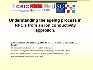
Understanding the ageing process in RPC’s from an ion conductivityapproach. C. Pecharromán1 , M. Morales2, G. Mata-Osoro1 , L. A. Díaz3 , V. Valcárcel4, J. A.Garzón2 1-Instituto de Ciencia de Materiales de Madrid (CSIC), Spain. 2-Centro de Investigación en Nanomateriales y Nanotecnología (CINN), (CSIC), Spain. 3-LabCaF, Facultad de Física, Universidad de Santiago de Compostela (USC), Spain. 4-Instituto de Cerámica de Galicia (ICG), Spain
Physical requirements for the resistive plate of a high rate timing RPC (for instance CBM demands 20 kHz/cm2) • Resistivity~ 109Wm. • Breakdown field Ev>>>1MVm-1 (1000V/mm) • Thermal Stability. • Not a very high permittivity • I/V ohmic if possible (R field independent) • Easy to fabricate and not very expensive.
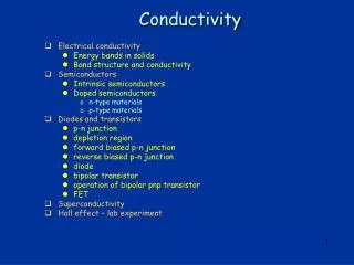
Conductivity of materials • Intrinsic materials are divided into insulator and conductors. • Materials in the range of 10-9W-1m-1 are limited:
) 7 10 -1 m f -1 4 10 (W c 1 10 -2 Concuctivity 10 -5 10 -8 10 -11 10 -14 10 0.0 0.1 0.2 0.3 0.4 0.5 0.6 0.7 0.8 0.9 1.0 f Ceramic/Metal insulators • Physical Mixtures of substances with very different conductivities. • The conductivity of these materials changes brusquely around the percolation threshold. • Heterogeneities in composites with concentration close to the percolation threshold spoil their properties. • Samples presented good homogeneity • Good conductivity values. • Samples can be machined. C. Pecharromán et al. Adv. Mater, 12, 294 (2000)
An example, Ni/BaTiO3 composites • Schottky and Tunneling conductivity behavior. • Detected areas of very large electric fields (hot spots) • Samples suffer breakdown process at a certain Vc value. C. Pecharromán et al. Adv. Mater, 13, 1541 (2001) R. Jimenez et al., Ferroelectrics 268 807 (2002) C Pecharromán et. al. Ferroelectric (2010)
Conduction models for metal/insulator interfaces T independent Log(I)~V1/2 electronic I~V, Arrhenius Log(I)~V1/2
Metal Metal Insulator Metal Metal Insulator Metal/ceramic composites under strong electric fields. • Metallic phase is a good electronic field • Potential only drops in insulator regions. Electron conductivity ion conductivity
Mo/Mullite Composites • Why Mullite/Molybdenum? • Mullite is an aluminum-silicate. • Its crystalline structure includes oxygen vacancies • It has a very high dielectric strength • It has the same expansion coefficient as Mo • Mo is a refractaire metal. • It is relatively stable against oxidation. • Processing of powders is quite simple. Mullite Hartmut Schneider (Editor), Sridhar Komarneni (Editor)
200 µm Mo/Mullite Composites • Electrical properties of Mu/Mo composites • I/V curves seem to indicate a space charge displacement mechanism. (I~V2). • Conductivity is very sensitive to temperature. • I/T indicates a thermal activated mechanism. • An ion conduction mechanism, at high fields is proposed.
r =4.9·1010W m • =1.37·10-23W m V-1 For float glass Mo/Mullite Composites SCD • Ohmic+space charge displacement model Ohm • r =3.6·108W m • =3.13·10-19W m V-1
Mo/Mullite Composites ageing • Ageing behaviour • Ressitance presents a strong temperature dependant behaviour. • Slight temperature peaks induce ireverssible resistance increments.
E Strutural images of mullite and glasses. Faradaic ion-defect current Electrochemical Breakdown Na+, K+ cations in glasses http://www.themolecularuniverse.com/ ISAACS, Se´bastien Le Roux* and Valeri Petkov*, J. Appl. Cryst. (2010). 43, 181–185
Simple model for composite electrochemical breakdown • Time to induce a structural atomic failure by faradic current • conductivity stops and atomic structure will collapse when a critical fraction of carriers abandon their equilibrium position . The fraction between total charge QTand charge defects Q is called h (tolerance to faults in the crystalline structure). • For crystalsh=10-5 ~ 10-17. Assuming r =109Wm and h=10-11 then t is around some days • For a glass with s =10-11W-1m-1hmay vary many orders of magnitude. An intermediate value is h=10-12 which results t around of years
Glass ageing • Ageing behaviour • Resistance presents a strong temperature dependant behavior. • Slight temperature peaks induce irreversible resistance increments. • The damage degree is smaller than in the case of Mu/Mo composites
Pecharroman C, PCCP, 11 5922 (2009) Deffects and hot spots. • In a composites, processing deffects modify localy the metal concentration, and therefore the conductivity • In a near percolated system, in some points the electric field can reach very high values – Hot Spots. • In those Hot Spots, the material can suffer dielectric breakdown in these area. 100 µm mMu/Mo=3.13·10-19W m V-1 mglass=1.37·10-23W m V-1
) 7 10 -1 m f -1 4 10 c (W 1 10 -2 10 Concuctivity -5 10 -8 10 -11 10 -14 10 0.0 0.1 0.2 0.3 0.4 0.5 0.6 0.7 0.8 0.9 1.0 f New proposal. • Mixtures formed by insulators and electron conductors (transition metal oxides) slightly above the percolation threshold. Electronic conduction from oxygen defects in transition metal oxides (Fe, Zn, Sn, Ni, Ti, etc). Conductor Ceramic/Insulator ceramic Metal/ceramic
Commercial ferrite behaviour • Linear I/V response (Ohmic). • Conductivity does not vary so much with T. • No ageing. • Too much conductivity (up to now)
Conclusions • Mu/Mo composites, with metal concentration below fc presents good s values for RPC materials, nearly ohmic behavior and high breakdown field. • However, electrochemical ageing increases its resistance until breakdown happens after several days. • Ion conduction must be avoided for long term operation. Only defective-tolerant atomic structures may work reasonably (float glass) • Possible solution: transition metal oxide ceramics (Fe, Ni, Ti, Zn, Sn, Co, etc) with conductor phases slightly above the percolation threshold.