Design and Optimization of the BDS Lattice for the ILC: Minimal Machine and Operational Enhancements
160 likes | 284 Vues
This document outlines the design principles, proposed alterations, and implications for the Beam Delivery System (BDS) lattice at the International Linear Collider (ILC). Key discussions include minimal machine layouts, various design constraints, upgrade paths, and diagnostics for beam extraction. The design focuses on initial operation at 250GeV, with a potential upgrade to 500GeV through additional magnets. Special attention is given to emittance growth and layout adjustments accommodating different beam sources and extraction strategies.

Design and Optimization of the BDS Lattice for the ILC: Minimal Machine and Operational Enhancements
E N D
Presentation Transcript
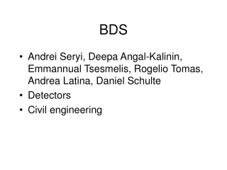
BDS optics and minimal machine study Deepa Angal-Kalinin ASTeC & The Cockcroft Institute Daresbury Laboratory LCWS08/ILC08
Contents • RDR BDS Design • Minimal machine • Proposed changes and implications to the BDS lattice design • Layout possibilities • Constraints • Design criteria • Upgrade path • Discussion LCWS08/ILC08
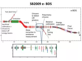
RDR BDS Design Linac Exit Beam Switch Yard Diagnostics Sacrificial collimators b-collimator E-collimator Final Focus Tune-up & emergency Extraction 14mr IR Tune-up dump Total length, BDS : 2226m Tune-up/fast extraction line : 467m Post collision extraction line: 300m Muon wall Main dump Extraction grid: 100m*1m LCWS08/ILC08
BDS RDR Design Criterion • Initial operation at (up to) 250 GeV; upgrade to 500 GeV by adding magnets only • no layout/geometry changes (beam dumps locations fixed) • Decimate dipoles : reduce ∫Bdl for 250 GeV operation by reducing lengths (i.e. number of dipoles); reserve space for additional dipoles to keep layout fixed • Quadrupoles & sextupoles unchanged • reduce ∫Gdl for 250 GeV operation by reducing strengths • Final Doublet magnets will have to be replaced for 500 GeV • Final Focus: 12 m “soft” bends divided into 5 × 2.4 m pieces • start with center piece only at each location • space reserved for remaining 4 pieces at each location for 500 GeV • Synchrotron Radiation Emittance Growth (DIMAD tracking; SYNC option 2) @ 250 GeV, emit/emit0 = 1.0036 @ 500 GeV, emit/emit0 = 1.0078 http://www.slac.stanford.edu/~mdw/ILC/2006e/doc/BDS2006e.ppt LCWS08/ILC08
Hybrid & Minimal (250 GeV) layouts Llinac→IP = 2226 m 19th September’06, ILC@SLAC BDS meeting Llinac→IP = 1530 m A.Seryi, Y. Nosochkov, M. Woodley LCWS08/ILC08
ILC2006s : Lattice details Llinac→IP = 1530 m Tune-up/Fast extraction: 318m A.Seryi, Y. Nosochkov, M. Woodley LCWS08/ILC08
ILC2006s : Optics ISR: Δεx/εx0 = 0.5 % A.Seryi, Y. Nosochkov, M. Woodley LCWS08/ILC08
Central Region Integration • Undulator-based positron source moved to end of linac (250 GeV point) • e+ and e- sources share same tunnel as BDS • upstream BDS (optimised integration) • Including 5GeV injector linacs • Removal of RDR “Keep Alive Source” • replace by few % ‘auxiliary’ source using main (photon) target • 500 MV warm linac, also in same tunnel • Damping Rings • in BDS plane but horizontally displaced to avoid IR Hall • Injection/Ejection in same straight section • Circumference • 6.4 km (current RDR baseline) • 3.2 km (possible low-P option) LCWS08/ILC08
Undulator location • Changes in BDS layout to accommodate this • Dogleg to provide clearance for the e+ photon target • TESLA design : switchyard to allow photons to the target as well as beam to second IR. LCWS08/ILC08
Dogleg : TESLA • 100 m for undulator + 300 m photon beam line (proposed 400m for ILC to reduce the offset of dogleg) • TESLA Transverse clearance at target (60cm) • Need more for ILC ? (remote control, 1m transverse concrete shielding). • ~100cm (need exact number). • Beam pipe can pass through this shielding but without any component LCWS08/ILC08
TESLA : emittance growth Horizontal emittance growth for the entire BDS, and a beam energy of 400 GeV (design emittance gex = 8 x 10⁻⁶ m). 14% emittance growth was considered to be acceptable. LCWS08/ILC08
Positron Source & BDS integration Existing 1TeV geometry BDS Some optimisation is available Longer photon drift to target would facilitate smaller transverse offset of primary e- dogleg TENTATIVE EXAMPE (WIP) N. Walker, Positron Source Workshop 29/10/08 LCWS08/ILC08
Layout possibilities • Fast extraction/tuning before undulator? This will protect the small aperture of the undulator. • Beam diagnostics (coupling correction and emittance measurement section) before the undulator? • before dogleg – no bends and tune-up dump • laser wire photon detection? • Polarisation measurement – probably better after the undulator? • Will need dedicated chicane for fast extraction : will add to the overall length. LCWS08/ILC08
Design Criterion • Dogleg : design criterion • How much emittance dilution is acceptable? • ISR emittance growth for ILC2006s (no dogleg) is 0.5% (criterion?) • Can dogleg be combined with energy collimation? • Order of collimation will be energy, betatron => collimation performance • Location of muon wall (possible DR injection) • Can we change the spoiler survival criterion to 1 bunch at 250 GeV? • Locations of energy and polarisation measurements LCWS08/ILC08
Upgrade path • Beam dump locations cannot be changed • Consider if having only one beam dump for tuning + post collision will save cost. • To extend the BDS backwards will not be possible due to undulator location? • To discuss… LCWS08/ILC08