
Single-Slit Diffraction: Huygens' Principle Explained
E N D
Presentation Transcript
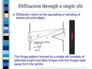
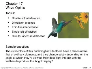
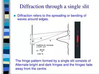
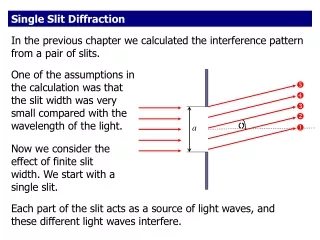
Single-Slit Diffraction • Single-slit diffraction is diffraction through a tall, narrow slit of width a. • The light pattern on the viewing screen consists of a central maximum and a series of weaker secondary maxima and dark fringes. • The central maximum is much broader and brighter than the secondary maxima.
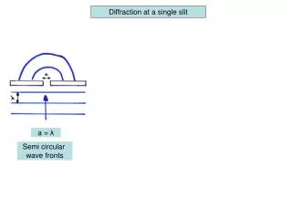
Huygens’ Principle • To understand diffraction, we need to think about the propagation of an extended wave front. • The Dutch scientist Christiaan Huygens developed a geometrical model to visualize how any wave, such as a wave passing through a narrow slit, evolves.
Huygens’ Principle Huygens’ Principle has two parts: • Each point on a wave front is the source of a spherical wavelet that spreads out at the wave speed. • At a later time, the shape of the wave front is the curve that is tangent to all the wavelets.
Huygens’ Principle • The curve tangent to the wavelets of a plane wave is a plane that has propagated to the right.
Huygens’ Principle • The curve tangent to the wavelets of a spherical wave is a larger sphere.
Analyzing Single-Slit Diffraction • According to Huygens’ Principle, each point on the wave front can be thought of as the source of a spherical wavelet. • These wavelets overlap and interfere producing the diffraction pattern seen on the viewing screen.
Analyzing Single-Slit Diffraction • The paths of several wavelets as they travel straight ahead to a central point on a screen are nearly parallel, and so they are in phase. • Constructive interference will occur, creating the central maximum of the diffraction pattern at= 0.
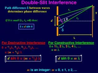
Analyzing Single-Slit Diffraction • At points away from the center of the screen, interference occurs. • Wavelets 1 and 2 start a distance of a/2 apart. If Δr12 is λ/2 then the wavelengths are out of phase and interfere destructively. • If Δr12 is λ/2, then so are Δr34 and Δr56, so perfect destructive interference occurs.
Analyzing Single-Slit Diffraction • Every point on the wave front can be paired with another point that is a distance a/2 away. • The condition for destructive interference is
Analyzing Single-Slit Diffraction • The general condition for complete destructive interference is a sin p = pp = 1, 2, 3,. . . • Using the small angle approximation, the condition is written • p= 0 is specifically excluded because p= 0 is the central maximum. The equation for all other p’s locates the minima.
Analyzing Single-Slit Diffraction • The bright central maximum at = 0 has the highest intensity.
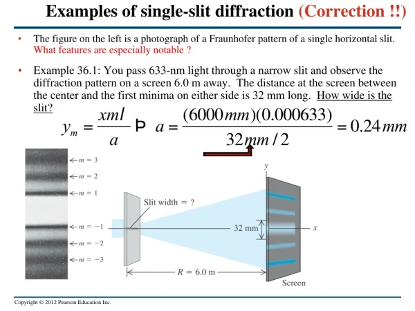
The Width of the Single-Slit Diffraction Pattern • The dark fringes in the single-slit diffraction pattern are located at
The Width of the Single-Slit Diffraction Pattern • The width w of the central maximum is defined as the distance between the two p = 1 minima, which is simply w = 2y1. • Counterintuitively, the smaller the opening a wave squeezes through, the more it spreads out on the other side.
Question 1 • A laboratory experiment produces a single-slit diffraction pattern on a screen. If the slit is made narrower, the bright fringes will be • Closer together. • In the same positions. • Farther apart. • There will be no fringes because the conditions for diffraction won’t be satisfied.
p L Minima between the bright fringes are at . y p a Question 1 • A laboratory experiment produces a single-slit diffraction pattern on a screen. If the slit is made narrower, the bright fringes will be • Closer together. • In the same positions. • Farther apart. • There will be no fringes because the conditions for diffraction won’t be satisfied.
Question 2 • Each of the slits is separately illuminated by a broad laser beam. Which produces a broader brightly illuminated region on the screen at the right? • The 1-cm-wide slit • The 2-cm-wide slit
Question 2 • Each of the slits is separately illuminated by a broad laser beam. Which produces a broader brightly illuminated region on the screen at the right? • The 1-cm-wide slit • The 2-cm-wide slit
Question 3 • A laboratory experiment producesa double-slit interference pattern on a screen. If the left slit is blocked, the screen will look like
Question 3 • A laboratory experiment produces a double-slit interference pattern on a screen. If the left slit is blocked, the screen will look like D.
Question 4 • A laboratory experiment produces a single-slit diffraction pattern on a screen. The slit widthis a and the light wavelength is . In this case, • a • a • a • Not enough info to compare to a
Question 4 • A laboratory experiment produces a single-slit diffraction pattern on a screen. The slit width is a and the light wavelength is . In this case, • a • a • a • Not enough info to compare to a