MT-284 MANUFACTURING PROCESSES
MT-284 MANUFACTURING PROCESSES. INSTRUCTOR: SHAMRAIZ AHMAD MS-Design and Manufacturing Engineering Shamraiz_88@yahoo.com Topic: Sheet Metal Working (Part-2). Sheet Metal Bending (Last Lecture). Straining sheetmetal around a straight axis to take a permanent bend.

MT-284 MANUFACTURING PROCESSES
E N D
Presentation Transcript
MT-284MANUFACTURING PROCESSES INSTRUCTOR: SHAMRAIZ AHMAD MS-Design and Manufacturing Engineering Shamraiz_88@yahoo.com Topic:Sheet Metal Working (Part-2)
Sheet Metal Bending (Last Lecture) Straining sheetmetal around a straight axis to take a permanent bend Figure 20.11 (a) Bending of sheet metal
This Lecture • Sheet metal work – Bending (Forming) • Engineering Analysis of Bending • Other Forms of Bending • Sheet metal work – Drawing (Forming) • Introduction to drawing operation • Engineering Analysis of drawing • Other Forms of drawing • Defects in drawing • Some other Sheet metal forminng operations
Engineering Analysis of Bending • Bending radius R is normally specified on the inside of the part, rather than at the neutral axis. The bending radius is determined by the radius on the tooling used for bending. • Bending Allowance: If the bend radius is small relative to sheet thickness, the metal tends to stretch during bending. Knowledge about Stretching is important to have final part length according to specified dimensions. • It is about determining the length of neutral axis before bending, in accordance with final bend length. The bend allowance (BA) is the length of the arc of the neutral line between the tangent points of a bend in any material. • BA = 2pA(R + Kbat)/360 • Where BA – bend allowance(mm); • A - bend angle, degrees; • R – bend radius, in. (mm); • t – sheet thickness; and • Kba - factor to estimate stretching. if R < 2t, Kba= 0.33; and if R>=2t, Kba =0.5.
Engineering Analysis of Bending Spring back: When the bending pressure is removed at the end of deformation, elastic energy remains in the bend part, causing it to recover partially toward its original shape. SB = (A’ – Ab’)/Ab’ Where SB – springback; A’ – included angle of sheet-metal part; and Ab’ – included angle of bending tool, degrees.
Engineering Analysis of Bending Bending Force: The force required to perform bending depends on the geometry of the punch and die and the strength, thickness, and width of the sheet metal. The maximum bending force can be estimated by means of the following equation based on bending of a simple beam: F = (KbfTSwt2)/D Where F – bending force, lb (N),; TS – tensile strength of the sheet metal, lb/in2. (Mpa); t – sheet thickness, in. (mm); w- width of sheet metal and D – die opening dimension. Kbf – a constant that counts for differences in an actual bending processes. For V-bending Kbf =1.33, and for edge bending Kbf =0.33
Bending Problem Metal to be bent with a modulus of elasticity E = 30x106 lb/in2., yield strength Y = 40,000lb/in2 , and tensile strength TS = 65,000 lb/in2. Determine (a) starting blank size, and (b) bending force if V-die will be used with a die opening dimension D = 1.0in. (a) W = 1.75’, and the length of the part is: 1.5 +1.00 + BA. R/t = 0.187/0.125 = 1.5 < 2.0, so Kba=0.33 For an included angle A’ = 1200, then A = 600 BA = 2pA(R + Kbat)/360 =2p60(0.187 + 0.33 x 0.125)/360 = 0.239” Length of the bank is 1.5+1+0.239 = 2.739” (b) Force: F = (KbfTSwt2)/D = 1.33 (65,000)(1.75)(0.125)2/1.0 = 2,364 lb
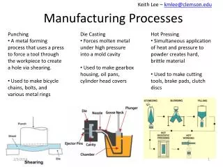
Other Bending Operations Other bending operations include:( Different from basic bending due to curved axis and other different features) a. Hemming involves bending the edge of the sheet over onto itself in more than one bending step. This process is used to eliminate sharp edges, increase stiffness, and improve appearance, such as the edges in car doors. b. Seaming is a bending operation in which two sheet metal edges are joined together. c. Curling (or beading) forms the edges of the part into a roll. Curling is also used for safety, strength, and aesthetics. • Hemming • Seaming • Curling
Other Bending Operations d. Flanging is a bending operation in which the edge of a sheet metal is bent at a 90° angle to form a rim or flange. It is often used to strengthen or stiffen sheet metal. The flange can be straight, or it can involve stretching or shrinking as shown in the figure below: • Straight flanging • Stretch flanging • Shrink flanging
3. Drawing Operation Definition: Drawing is a Sheet metal forming to make cup‑shaped, box‑shaped, or other complex‑curved, hollow‑shaped parts . The Sheet metal blank is positioned over die cavity and then punch pushes metal into opening. • Products: beverage cans, ammunition shells, Cooking parts, automobile body panels
Drawing Operation (a) Drawing of cup‑shaped part: (1) before punch contacts work, (2) near end of stroke; (b) workpart: (1) starting blank, (2) drawn part.
Drawing Parameters Clearance in Drawing • Sides of punch and die separated by a clearance c given by: the clearance in drawing is about 10% of the stock thickness. c = 1.1 t where t = stock thickness • In drawing as the punch moves downward, the stock goes under complex stresses and strains and is formed into the shape defined by punch and die.
Drawing Parameters Friction: The force being applied by punch is opposed by the metal in form of deformation and friction in the operation. • Lubricants are generally used to reduce the friction
Drawing Parameters Blank holding force: • If this force is too small, the wrinkling occurs. • If it is too large, it prevents metal from flowing properly towards die cavity, resulting in stretching and possible tearing of sheet metal. • Determining proper holding force involves a delicate balance between these opposing factor.
Engineering Analysis of Drawing Tests of Drawing Feasibility These tests provides information about feasibility of the drawing operation before actually performing the operation. • Drawing ratio • Reduction • Thickness-to-diameter ratio
Engineering Analysis of Drawing 1. Drawing Ratio DR The DR measures the severity of drawing operation. The greater the ratio, the more severe the operation. Most easily defined for cylindrical shape: where Db = blank diameter; and Dp = punch diameter • Upper limit: DR 2.0 (operation feasible)
Engineering Analysis of Drawing 2. Reduction R: • Defined for cylindrical shape: • Value of r should be less than 0.50 • 3. Thickness‑to‑DiameterRatio t/Db • Thickness of starting blank divided by blank diameter • Desirable for t/Db ratio to be greater than 1 • As t/Db decreases, tendency for wrinkling increases
Engineering Analysis of Drawing • Drawing Forces • The force required to perform drawing operation. • F= Drawing Force, Db= Blank diameter, Dp= Punch Diameter • t= Original blank thickness, TS= Tensile thickness • 0.7 is correction factor to account for friction during operation • Drawing force varies throughout the downward movement of the punch and usually reaches maximum at about one-third the length of the punch stroke.
Other Drawing Operations 1. Redrawing • When too severe shape change is requires ( high drawing ratio), complete forming may require more than one drawing steps. • The second drawing step, and any further steps required, are referred to as redrawing. 2. Drawing without Blank holder • The blank holder is used to prevent wrinkling of the flange while cup is being drawn. • Tendency of wrinkling reduces as t/Db ratio increases • So, when this ratio is large, the drawing can be done without blank holders • Governed by [ 5t > Db-Dp ] • Without blank holder cost of tooling decreases and simple press can be used.
Other Drawing Operations 3. Shapes other than Cylindrical Cups • Many shapes other than cylinder are also drawn. • Square or rectangular boxes • Stepped cups • Cones • Cups with spherical rather than flat bases • Irregular curved forms (as in automobile body panels) Each of these shapes presents its own unique technical problems in drawing
Defects in Drawing 1. Wrinkling in the flange • Wrinkling is a major defect in drawing operation. • The movement of the blank into the die cavity induces compressive stress in the flange causing series of ridges radially on undrawn part of flange. • This can be reduced by keeping a blank holder under the effect of a holding force 2. Wrinkling in the wall • When the flange is drawn into cup, these ridges appears into the vertical wall. • t/D ↑ or Fh ↑ Wrinkling ↓ 3. Tearing • It is an open crack in the vertical wall, usually near the base of drawn cup which is caused due to thinning and failure of metal in this location. • It may also occur due to pulling metal over sharp die corner.
Defects in Drawing 4. Earing • This is the formation of irregularities (called ears) in the upper edge of the deep drawn, caused by anisotropy in the sheet metal • If material is perfectly isotropic the earing does not occur. 5. Surface scratch • Scratches on surface of drawn parts appear when surface of die and punch are not smooth or sufficient lubricant is not used.
4. Other Sheet Metal Forming on Presses In addition to bending and drawing, several other sheet metal forming operations performed on conventional presses. This includes; • Ironing (using metal tooling) • Embossing (using metal tooling) • Hydro forming (using rubber forming approach)
1. Ironing • A process which makes wall thickness of cylindrical cup more uniform and it is normally done after drawing • Beverage canes and artillery shell are ironed to increase the life of material usage (1) start of process; (2) during process. Note thinning and elongation of walls.
2. Embossing • Creates indentations in sheet, such as raised (or indented) lettering while maintaining the stock thickness uniform Embossing: (a) cross‑section of punch and die configuration during pressing; (b) finished part with embossed ribs.
3. Hydro forming • Hydroforming is a specialized type of die forming that uses pressurized hydraulic fluid in a diaphragm to form typical metallic sheets in to a desired shape with a die cavity. Hydroforming is a cost-effective way of shaping malleable metals such as aluminium or brass into lightweight, structurally stiff and strong pieces.
Assignment # 02 Individual 6-pages assignment on “Group Technology and Flexible Manufacturing System” Last date of submission: 16-05-2014