Download
1 / 37
380 likes | 761 Vues
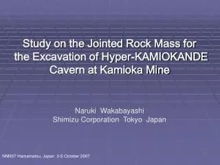
Study on the Jointed Rock Mass for the Excavation of Hyper-KAMIOKANDE Cavern at Kamioka Mine. Naruki Wakabayashi Shimizu Corporation Tokyo Japan. NNN07 Hamamatsu, Japan 3-5 October 2005. Topics ・ Previous Geological Survey and Stability Analysis for the Hyper-K cavern

E N D
Study on the Jointed Rock Mass for the Excavation of Hyper-KAMIOKANDE Cavern at Kamioka Mine Naruki Wakabayashi Shimizu Corporation Tokyo Japan NNN07 Hamamatsu, Japan 3-5 October 2005
Topics ・Previous Geological Survey and Stability Analysis for the Hyper-K cavern ・Site Selection ・Isotropic Elastic FEM Analysis for the Investigation of Cavern Shape, Size and Type ・Ongoing Investigation and Analysis for Jointed Rock Mass ・Investigation of Joint Orientation ・Obtaining In-Situ Rock Joints and Investigation of Joint Mechanical Properties ・Pull-out Test of Two Types of Cable Bolt ・Two TypeAnalysis for Consideration Joint Effects
Kamioka Mine Tokyo Hamamatsu Site Selection Kamioka Mine Location Mozumi mine Super-K Proposed Area Proposed Area in Mozumi Mine is about 10km South from the Super-Kamiokande. Tochibora mine
Geological Map of Proposed Siteat Tochibora MinePlan View of + 550mEL Core Boring ”NAMARI” Fault Limestone Hyper-K proposed Site Hornblende Biotite Gneiss & Migmatite Skarn Orebody Zone Existing Tunnel Surveyed ”ANKO” Fault Biotite Gneiss ”240゜- ME” Fault Proposed Site Formation is Hornblende Biotite Gneiss and Migmatite. N
”NAMARI” Fault Offset ”ANKO” Fault Spacing ”240°-ME” Fault Isotropic Elastic FEM Analysis Cylindrical Dome Larger than Super-K Two Parallel Tunnels Huge Tunnel Comparison of the Hyper-K Cavern from Various View Points Image Design of Two 250m Long Parallel Tunnels
Summary ofPrevious Study Site Selection : Tochibora Mine, +480mEL~+550m EL is the most appropriate location with very competent rock condition. Cavern Design: Two 250m Long Parallel Tunnels with Section of 2,076m2 are capable of being safely excavated. Cavern Layout: Two Parallel Tunnels as above should be Located with 80m –100m Spacing and 50m-100m Offset to avoid the poor Zone of Surrounding Faults. In Isotropic Elastic FEM Analysis of Previous Study,Young’s Modulus was empirically decreased as Jointed Rock Mass. It is Important and Necessary to Consider Numerically the Influence of Joint Orientation and Mechanical Properties.
Equivalent Continuum Analysis Discontinuous Analysis Composition of Elastic Blocks Surrounding Joints Anisotropic Young’s Modulus Considering Joint Orientation and Mechanical Properties Key Block Damage Tensor Distinct Element Method (DEM) Crack Tensor Analysis for Jointed Rock Mass ・Characteristics of Joint Orientation ・Mechanical Properties of Joint and Rock Core ・Mechanical Properties of Support such as Cable Bolt
Measurement of Joint Orientation in this Existing Tunnel Rock Types Gneiss Migmatite N +550m EL Rock Classification B Very Good CH Good CM Medium Obtaining Rock Joint (3 Places) Pull-out Test of Cable bolt (6 Places) Investigation of Jointed Rock Mass
N N N N Migmatite Gneiss E E E E W W W W Strike Joint N W E Pole S S S S S Dip × Investigation of Joint Orientation ・Major Joint Set: Strike E-W and Dip ±70~90° ・Another Joint Set : Strike NE-WS and Dip ±40~50° Projection of Poles Pole Density Contours
Situation of Obtaining In-Site Rock Joints Diamond Drilling Joint Recovered Core with Joint Joint
Joint Mechanical Properties Direct Shear Test of Rock Joints ・Joint Deformability Parameters such as Normal and Shear Stiffness, Dilatancy Angle ・Joint Shear Strength such as Cohesion and Internal Friction Angle Rock Joint Specimen with extensometers Normal Stress Shear Displacement Shear Test Equipment (Normal and Shear load are 1MN)
σn=10N/mm2 Cohesion=0.57N/mm2 Internal Friction angle =33° Shear Strength (N/mm2) Normal Stiffness =67N/mm2/mm Normal Stress (N/mm2) Normal Displacement (mm) Shear Stiffness=60N/mm2/mm Shear Strength Shear Stress (N/mm2) Normal Displacement (mm) Dilatancy angle=2.4° Shear Displacement (mm) Shear Displacement (mm) Results of Direct Shear Test Normal Stress (N/mm2)
Special Cable Bolt with Dimples (ST-Cable Bolt) Usual Cable Bolt without Dimples (PC-Cable Bolt) Pull-Out Test of Two Type Cable Bolts Economical Support System should be used ・Usual Support System for Large Cavern is Rock Anchor → Expensive ・Proposed Support System is Rock Bolt and Cable Bolt → Economical ・Special Cable Bolt with Dimples has very high Strength ・Mechanical Properties of Cable bolt was estimated by Pull-Out Test
Inserting Cable Bolts Diamond Drilling ST-Cable Bolt PC-Cable bolt Pull-Out Test Setting up Equipments Jock and Dial Gauge Pressure Pump Situation of Pull-Out Tests
Cable bolt model Strength (kN/m) Stiffness (kN/m/m) Migmatite (B) ST △Gneiss (CH) ○Migmatite(CH) △Gneiss (CH) ○Migmatite(CH) □Gneiss (B) ◇Migmatite(B) □Gneiss (B) ◇Migmatite(B) ST Stiffness (kN/m/m) PC ST Strength above 270kN/m Stiffness above 53MN/m/m Load (kN) PC Strength above 53kN/m Stiffness above 40MN/m/m PC Strength (kN/m) Displacement (mm) Results of Pull-Out Tests Gneiss (B) ST Load (kN) PC Displacement (mm)
Huge Tunnnel W48m×H54m 2070m2 Discontinuous Analysis by DEM DEM Analysis is Performed to Establish the Behavior of Jointed Rock Mass and the Effect of Support System. Cavern Direction is East and West Cavern Type and Direction Analysis Cases
200m Second Step First Step 200m Strike E-W Dip ±70~90° Strike NS-WS Dip ± 40~50° Third Step Fourth Step Procedure of Analysis Analysis Model Joints are Generated Statistically According to the Joint Orientation Establishing Support System after Each Excavation Step
(kN) (kN) 45 35 32 93 41 37 618 464 415 620 89 67 60 17 13 13 284 474 (mm) (mm) 17 10 10 15 15 15 Case 1:Without Support Case 2:RB+PC-Cable Bolt (Double) Failure × (mm) Displacement Vector and Cable Axial Force Displacement of Right and Left Side Wall are nearly same because of Symmetrical Joint Dip Angle (±70~90°). Displacement of Case-3 is smaller than Case-2 because of Support Effect Case 3: RB+ST-Cable Bolt (Double)
Joint Strike Joint Strike Case 1 Case 2 234m Huge Tunnnel W48m×H54m 2070m2 240m 48m 240m 54m Z 240m X Cavern Type and Region (528m×528m) Model Equivalent Continuum Analysis by Crack Tensor Crack Tensor Analysis is Performed to Estimate the Relation between Tunnel Direction and Joint Orientation. In-Situ Stress is Isotropic σH=σv=14.4 (N/mm2) Case 1:Cavern Direction is East and West, parallel Joint Strike Case 2:Cavern Direction is North and South, right-angled Joint Strike
Joint Strike Joint Strike Case 1 Case 2 Displacement Side Wall Displacement of Case 1 is 2 times Larger than Case 2 because of influence of Joint Strike Direction.
Summary Joint Orientation : At Proposed Site in Tochibora Mine, Major Joint Set Strike Direction is E-W and Dip Angle is ±70~90° Joint Properties : Normal and Shear Stiffness, Shear Strength are Estimated. Cable Bolt Properties: Shear Strength and Stiffness of ST and PC Cable Bolt are Estimated. Shear Strength of ST-Cable Bolt is 5 Times Higher than PC-Cable Bolt. ST-Cable Bolt is very Effective Support. Results of Analysis : Discontinuous and Equivalent Continuum Analysis are able to Estimate the Effect of Rock Support System and the Anisotropic Behavior of Jointed Rock Mass. Joint Orientation is very Important factor to decide the Cavern Axis. Further Investigation : It is Necessary for Accurate Joint Orientation to investigate in Different Direction Tunnel or Bore Hole. Measurements of In-Situ Initial Stresses and In-Situ Tests on Rock Mass Deformability are indispensable.
200m 傾斜角(deg) 200m 傾斜角(deg) 空洞の安定解析 南北の鉛直面に亀裂傾斜を投影し、統計的に亀裂を発生させてモデルを作成
クラックテンソルによる不連続性岩盤の巨視的な応力とひずみ関係クラックテンソルによる不連続性岩盤の巨視的な応力とひずみ関係 クラックテンソルによる解析手法の概要
クラックテンソルの算定 ■三次元のNij , Nijkl ■F0の算定 ・調査坑道10mあたり4本の不連続面を想定 ・不連続面の寸法(等価円の直径r) 不連続面の面積:S=2.6m×2.6m=6.76m2 ・F0の算定 (1) (5) (6) (2) (7) ∴F0=1.0 (8) ■二次元断面上のNij , Nijkl ■二次元断面上のFij , Fijkl (3) (4) (9) (10) 1.原位置岩盤のクラックテンソルの決定
クラックテンソルによる不連続性岩盤の巨視的な応力とひずみ関係クラックテンソルによる不連続性岩盤の巨視的な応力とひずみ関係 クラックテンソルによる解析手法の概要
解析結果 等方弾性解析 8mm 9mm 36mm 18mm 52mm 39mm 18mm 52mm 39mm 47mm 12mm 15mm ケース3 ケース1 変形図(200倍) • 空洞軸を東西方向とするケース2では、二次元断面上の不連続面が鉛直方向(Z方向)に卓越するため • それに垂直な方向となるX方向に変形が大きく生じる変形モードとなる。 • 一方、空洞軸を南北方向とするケース3では、空洞軸方向に対して直交する不連続面が卓越するため、XZ方向の変形は小さく、空洞軸方向の変形が大きく生じる変形モードとなる。
① ① ① ② ② ② ④ ④ ④ ⑤ ⑤ ⑤ ③ ③ ③ ⑥ ⑥ ⑥ 解析結果 等方弾性解析 ケース1 ケース3 ケース2 最大主応力分布(N/mm2)
① ① ① ② ② ② ④ ④ ④ ⑤ ⑤ ⑤ ③ ③ ③ ⑥ ⑥ ⑥ 解析結果 等方弾性解析 ケース3 ケース1 ケース2 最小主応力分布(N/mm2)
解析結果 等方弾性解析 ケース1 ケース3 ケース2 安全率分布
ラフネスの定量的評価 亀裂面のラフネスを測定し、フラクタル次元を算出 ↓ JRCを評価
ラフネスの測定例(1) 片麻岩 Df=1.0071→JRC=12 Df=1.0264→JRC=24 Df=1.0302→JRC=26 Df=1.0121→JRC=16 片麻岩 Df=1.0072→JRC=12 Df=1.0082→JRC=13
ラフネスの測定例(2) 片麻岩 Df=1.0125→JRC=16 Df=1.0158→JRC=18 Df=1.0157→JRC=18 片麻岩 Df=1.0077→JRC=13 Df=1.0117→JRC=16 Df=1.0108→JRC=15