Download
1 / 52
530 likes | 736 Vues
Chapters 8 OPTICAL PYROMETRY. “ … try adding minus one to the denominator … ” Max Planck (1900). 8.1 Historical Resume Gustav Kirchoff, in 1860, defined a black body as a surface that neither reflects nor passes radiation [1].

E N D
“ … try adding minus one to the denominator … ” Max Planck (1900)
8.1 Historical Resume Gustav Kirchoff, in 1860, defined a black body as a surface that neither reflects nor passes radiation [1]. He suggested that such a surface could be realized by heating a hollow enclosure and observing the radiation from a small times access hole (e.g. a cylindrical hole of a depth from five to eight times its diameter that radiates from one end closely approximates black body). Kirchoff defined the emissivity E of a non-black body as the ratio of its radiant intensity to that of a similar black body at the same.
Henri LeChatelier introduced, in 1892, the first practical optical pyrometer. It included an oil lamp as the reference light source, a red glass filter to limit the wavelength interval, and an iris diaphragm to achieve a brightness match between the light source and the test body. Wilhelm Wien, in 1896, derived his law for the distribution of energy in the emission spectrum of a black body as (8.1)
Where J represents intensity of radiation emitted by a black body at temperature T, and wavelength λper unit wavelength interval, per unit time, per unit solid angle, per unit area. Max Planck, to remedy deviations that appeared between (8.1) and the experimental facts at high values of λT suggested, in 1900, the Mathematical expression to describe the distribution of radiation among the various wavelengths; that is, he simply added a -1 to the denominator of Wien’s equation . (8.2)
However , in attempting to explain the significance of -1 in the denominator , Planck developed the quantum theory ( where in he postulated that electromagnetic waves can exist only in the form of certain discrete packages or a quanta ). Subsequently he received the Nobel Prize for his work. The numerical values and the units, both in the International System (SI) and in the U.S. Customary System, for all the quantities involved in(8.2) are given in Table 8.1. An example illustrates the use of (8.2).
Example 1. Find the intensity of radiation emitted by a black body at 2200oR at a wavelength of 3μin both SI and U.S. Customary units, and check. U. S. Customary
That the SI answer checks the U. S. answer can readily be seen by applying several conversion constants .That is In 1927 the International Temperature Scale (ITS) was defined. Temperatures above the gold point (then 10630C) were to be given by Wien’s equation (8.1) used in conjunction with a disappearing filament optical pyrometer.
In 1948 the ITS was redefined so that temperatures above the gold point were to be given by Planck’s equation (8.2) and a disappearing filament optical pyrometer. This definition of the higher temperatures continues to the present (see Chapter 4). Note that in practice it is the spectral radiance of the test body (at its temperature) relative to that of a black body at the gold point that defines its temperature on the IPTS according to (4.4).
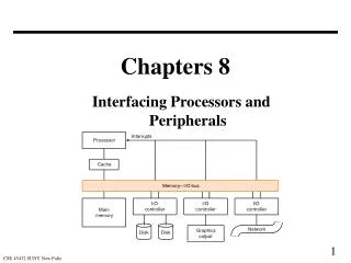
8.2 Principles of optical Pyrometry An optical pyrometer [2], [3] consists basically of an optical system and a power supply. The optical system includes a microscope, a calibrated lamp and a narrow band Wave filter, all arranged so that the test body and the standard light source can be viewed simultaneously. The power supply provides an adjustable current to the lamp filament (see Figures 8.1 and 8.2)
Optical pyrometry is based on the fact that the spectral radiance from an incandescent body is a function of its temperature [4],[5]. For black body radiation, the well-known curves of Plank’s equation describe the energy distribution as a function of temperature and wavelength (Figure 8.3). If a non-black body is being viewed ,however, its emissivity ,which is a function of wavelength and temperature, must be taken into consideration ( Figure 8.4 ). In general, to obtain the temperature of a test body, the intensity of its radiation at a particular wavelength is compared with that of a standard light source.
Red Filter The very narrow band of wavelengths required for the comparison just noted is established in part of the use of a red filter in the optical system, and in part by the observer’s eye. A red filter exhibits a sharp cutoff at λ=0.63μ(where 1μ=0.001mm) This means that below about 1400℉, the intensity of radiation transmitted by a red filter is too low to give adequate visibility of the test body and the standard filament. On the other hand, a red filter exhibits a high transmission for λ>0.65μ(see Figure 8.5), so that it is the diminishing sensitivity of the eye that provides the necessary cutoff at the high end of the band.
The particular wavelength that is effective in optical pyrometry is usually taken as 0.65μ Brightness Temperature Several steps are involved in determining temperature by an optical pyrometer [6], [7]. First, the brightness of the test body is matched against the brightness of the filament of a calibrated lamp at the effective wavelength of 0.655μ. Because the image is nearly monochromatic red, no color difference is seen between the lamp filament and the test body, and thus the filament seems to disappear against the background of the target. Of course, matching should be recognized as a null balance procedure.
It is the optical equivalent of a Wheatstone bridge balance to determine resistance measurements or a potentiometric balance for voltage measurements. Second, the filament current necessary for the brightness match must be measured. For the highest accuracy , this is best achieved by a potentiometric measurement across a fixed resistor in series with the lamp filament . Third , the filament current measurement , obtained at the match condition , must be translated into brightness temperature by means of a predetermined calibration relationship ( see Sections 8.3 ) .
This calibration is predicated on the existence of a lamp with a stable , reproducible characteristic with temperature and time. Finally , brightness temperature must be converted to actual temperature through applying the emissivity of the test body ( see Tables 8.2, 8.3 , and 8.4 as well as the examples that follow ) . The brightness temperature is defined as that temperature at which a blackbody would emit the same radiant flux as the test body. This is the temperature as observed with an optical pyrometer. For non-black bodies the brightness temperature is always less than the actual temperature. Thus according to Table 8.2 a black body(ε= 1)
would appear 1 . 1 times as bright as carbon(ε=0.9) 2.3 times as bright as tungsten (ε=0.43) and 3.3 times as bright as platinum(ε=0.3) when all are at the same temperature . To say it another way , the actual temperatures of these materials would be 2000oF for the black body , 2016℉ for the carbon , 2137℉ for the tungsten , and 2198℉ for the platinum , when all indicate a brightness temperature of 2000℉ ( according to Tables 8.2 , 8.3 , and 8.4 ) .
From Wien’s law , (8.1) , the relationship between the actual temperature (T) and the brightness temperature (TB) can be approximated in terms of the pyrometer’s effective wavelength of radiation(λ) the second radiation constant (c2) , and the target emissivity(ε) (8.3) If the transmission (τ) of the viewing effective emissivity (ε) should be used system in ( 8.3 ) is not unity , then the in place of the source
Of course, if ε=l and τ=l the actual temperature will equal the brightness temperature, since, according to (8.3), ln 1=0. Equation 8.3, with (8.4) factored in, is solved graphically in Figure 8.7, and tabularly in Tables 8.3 and 8.4. Several examples will illustrate the use of these graphs and tables.
Example 2 A target brightness temperature of 1600K is measured with an optical pyrometer having an effective wavelength of 0.655 μ At this wavelength the effective emittance of the target is determined to be 0.6. Estimate and check the true target temperature in degrees Celsius and in degrees Fahrenheit. Graphical Solution According to Figure 8.7a, at TB=1600K, and at ε= 0.6,ΔT=T-TB=62℃, Thus T=TB+ΔT=1662K Tabular Solution According to Table 8.4 , at = 1327℃ , And at ε= 0.6,ΔT=62℃, = Tabular Solution According to Table 8.4 , at
Graphical Solution According to Figure 8.7a, at TB=1600K, and at ε= 0.6,which checks the graphical solution. According to Tables 8.3 ,at TB=2421℉ and at ε=0.6 ΔT=112℉. Thus T=2421+112=2533℉ Or T=1662K . which checks the graphical solution. Numerical Solution For small temperature differences, by Wien’s law (8.1) which once more provides a close check to the graphical and tabular solutions.
Example 2. The clean surface of liquid nickel, when viewed through an optical pyrometer having the conventional effective Wavelength 0.655μ yields a brightness temperature of 2600℉. Estimate and check the true nickel temperature. .
TB =2600℉, Tabular Solution According to Table 8.3, at and with an effective emissivilty estimated to be 0.37, according to Table 8.1, = 257℉. Thus T= T = 2857℉. According to Table 8.4 , at TB = 1427℃, and ε=0.37 by doubleinterpolation = 143℃ Thus T=1427+143=1570℃= 2858℉ which is consistent with the Fahrenheit solution.
Graphical Solution According to Figures 8.7b , at TB= 1700K, and atΔT = 142℃ ε=0.37 Thus T=1427+142=1569℃=2856℉ which check the tabular solutions. Numerical Solution According to (8.5), which provides a fair check to the graphical and tubular solutions. Since Δtis large in this of example, the approximation (8.3) is not as reliable as for smaller Δt.
Brightness temperature thus depends on the sensitivity of the eye to differences in brightness, and on a knowledge of the mean effective wavelength of the radiation being viewed. It does not depend on the distance between the test body and the optical pyrometer, however. We must be sure that the radiation observed is that being emitted by the test body rather than reflected radiation, since there is no relationship between the temperature of a surface and the radiation it reflects. Also, smoke or fumes between the optical pyrometer and the target must be avoided as must dust or other deposits on the lenses, screens , and lamp windows .
Pyrometer Lamp Of all the elements in the optical pyrometer, the pyrometer lamp is the most important, since it provides the reference standard for all radiance measurements. The most stable lamps consist of a pure tungsten filament enclosed in an evacuated glass tube. The vacuum is necessary to minimize convection and conduction heat transfer effects. The tungsten is always annealed before calibration and, once calibrated, can be used typically for 200 hours before recalibration is required .
Although theoretically the optical pyrometer has no upper temperature limit, practically, for long term stability, the lamp filament cannot be operated above a certain current or brightness. This limit corresponds approximately to 1350℃. Absorbing Glass Filter Glass filters , which absorb some of the radiation being viewed , are used when temperatures higher than 1350℃ are being measured in order to reduce the apparent brightness of the test body to values that the filament can be made to match . Thus it is not necessary to operate the standard lamp filament at as high a temperature as would normally be called for by the brightness of the test body.
Such practice adds to the stability and life of the filament. The absorbing glass filters are inserted between the objective lens and the pyrometer lamp as shown in Figures 8.1 and 8.2. Thus a black body at a temperature above 1350℃ appears the same through the absorbing glass as another black body would appear in the same pyrometer without a screen at a temperature below 1350℃. In addition, use of the proper glass screen allows closer color matching between the pyrometer lamp and the attenuated source, and this leads to more precise brightness matching.
Black Body The emissivity of most materials is such a variable quantity and so strongly dependent on surface conditions [10] that it becomes almost mandatory to sight on the test body in a black body furnace. In lieu of laboratory-type testing in the highly favorable conditions of a black body furnace, one can often approximate a black body in field-type applications; For example, if the surface temperature of an incandescent material in a test rig is required, a small hole can be drilled directly into the surface for sighting purposes.
The hole depth should be about five times its diameter, as previously mentioned. Regardless of the emissivity of the hole walls, the multiple reflections inside the cavity makes the hole radiate approximately as a black body. Temperatures based on such techniques are almost certain to be more valid than temperatures based on flat surface sightings, as corrected by estimated surface emissivities. In any case, whenever black body conditions prevail, if the brightness match is achieved, and if the pyrometer is properly calibrated, then
Hot Gas Measurements The radiation characteristics of hot gases are not like those of hot solids in that gases do not emit a continuous spectrum of radiation. Instead, the emissivity of a gas exhibits a rapid variation with wavelength . That is gases which radiate or emit strongly only at certain characteristic wavelengths, correspond to absorption principles of radiation pyrometry lines (see entirely Figure 8.8). It is clear that different from those just de- scribed are called for in the temperature measurement of gases , and the appropriate literature should be consulted for further information [11] .
At least three types of calibration are to be distinguished in optical pyrometry. Primary This type of calibration is done only at the National Bureau of Standards [2], [12]. The filament current required to balance the standard lamp brightness against pure gold held at the gold point temperature in a black body furnace constitutes the basic point in the calibration. Higher temperature points are determined by a complex method that is detailed in NBS Monograph 41, and is based on the use of tungsten strip lamps and sectored disks. Representative uncertainties in achieving the IPTS by optical pyrometry are:±4℃ at the gold point,± 60℃ at 2000℃ ; and 40℃ at ±4000℃.
In this type of calibration [3], [4] the output of a primary pyrometer(i.e., one calibrated at the NBS) is compared with that of a secondary pyrometer (i.e., one to be calibrated) when the pyrometers are sighted alternately on a tungsten strip lamp operated at different brightnesses. Such lamps are highly reproducible sources of radiant energy and can be calibrated with respect to brightness temperatures from 800 to 2300℃, with accuracies only slightly less than would be obtained according to the IPTS . Note that in this method the source need not be a black body so long as the pyrometers are optically similar.
Industrial Two secondary optical pyrometers can be intercompared periodically by sighting them alternately on the same source. Note that here the source need not be a black body and the comparison pyrometers need not have primary calibrations. The method is most useful for indicating the stability of the pyrometers, and thus can indicate the need for a more basic calibration. 8.4 The Two-Color Pyrometer The accuracy of a temperature determination by the single-color optical pyrometer just discussed is based on black body furnace sightings or on known emissivities.
A two-color pyrometer, on the other band, is used in an attempt to avoid the need for emissivity corrections. The principle of operation is that energy radiated at one color increases with temperature at a different rate from that at another color [13], [14]. The ratio of radiances at two different effective wavelengths is used to deduce the temperature. The two-color temperature will equal the actual temperature whenever the emissivity at the two wavelengths is the same. Unfortunately this is seldom true.
All that can be said is that when the emissivity does not change rapidly with wavelength, the two-color temperature may be closer to the actual temperature than the single-color brightness temperature. If the emissivity change with wavelength is large, however, the converse is true. Kostkowski [13] of the NBS indicates that, in any case, the two-color pyrometer is less precise than the single-color optical pyrometer, Typically, when both were sighted on a black body, the optical came within 2℃ of the known temperature, whereas the two-color pyrometer was on by 30℃.
8.5 Automatic optical Pyrometer Since 1956 the automatic optical pyrometer has dominated the field of accurate high-temperature measurement. In such an instrument, the pyrometer lamp current is adjusted automatically and continuously by detector that views alternately the target and the pyrometer lamp. Thus a brightness-temperature balance is achieved by the automatic optical pyrometer which, in principle, has considerably greater sensitivity and precision than a manually adjusted pyrometer that depends on the subjective judgment of the human eye (see Figure 8.9) [3], [9], [15].
Figures 8.9 Operational diagrams of (a) manually-adjusted optical pyrometer, and (b) automatic optical pyrometer (after Leeds and Northrup).