Download
1 / 61
750 likes | 1.6k Vues
Chapter (2). Hydraulic Power (pumps). Positive displacement pumps. Gear pumps. Vane pumps. Piston pumps. B-Vane pumps.

E N D
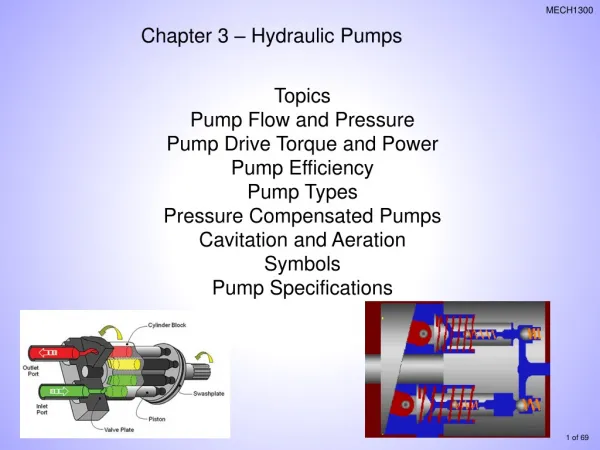
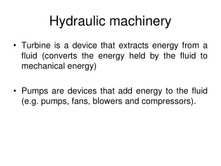
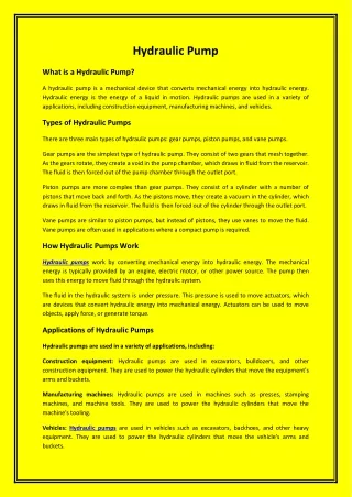
Chapter (2) Hydraulic Power (pumps)
Positive displacement pumps Gear pumps Vane pumps Piston pumps
B-Vane pumps The operation of the vane pump is based on , the rotor which contain radial slots rotate by a shaft and rotate in cam ring (housing), each slot contain a vane design as to comes out from the slot as the rotor turns. During one half of the rotation the oil inters between the vane and the housing then this area starts to decrease in the second half which permit the pressure to be produced , then the oil comes out pressurizes to the output port. Types of vane pump 1- Fixed Displacement vane pump 2- Variable Displacement vane pump
Vane pumps Fixed Displacement Vane pump Variable Displacement Vane pump Balanced Vane pump Unbalanced Vane pump
1- Fixed Displacement vane pump In this type of pump the eccentricity between pump cam-ring and rotor is fixed and pump discharge always remain same at a particular pressure. There are two types of fixed displacement Vane Pump:- 1- Unbalanced Vane Pump 2- Balanced Vane Pump
1- Unbalanced vane pump 1. A slotted rotor is eccentrically supported in a cycloidal cam. The rotor is located close to the wall of the cam so a crescent-shaped cavity is formed. The rotor is sealed into the cam by two sideplates. Vanes or blades fit within the slots of the impeller. .
1- As the rotor rotates (yellow arrow) and fluid enters the pump, centrifugal force, hydraulic pressure, and/or pushrods push the vanes to the walls of the housing. The tight seal among the vanes, rotor, cam, and side plate is the key to the good suction characteristics common to the vane pumping principle.
2. The housing and cam force fluid into the pumping chamber through holes in the cam (small red arrow on the bottom of the pump). Fluid enters the pockets created by the vanes, rotor, cam, and side plate. 3. As the rotor continues around, the vanes sweep the fluid to the opposite side of the crescent where it is squeezed through discharge holes of the cam as the vane approaches the point of the crescent (small red arrow on the side of the pump). Fluid then exits the discharge port.
Advantages 1- Handles thin liquids at relatively higher pressures 2- Compensates for wear through vane extension 3- Can run dry for short periods 4- Can have one seal or stuffing box 5- Develops good vacuum Disadvantages 1- Complex housing and many parts 2- Not suitable for high pressures 3- Not suitable for high viscosity
2- Balanced vane pump a balanced vane pump is one that has two intake and two outlet ports diametrically opposite each other. Pressure ports are opposite each other and a complete hydraulic balance is achieved. One disadvantage of the balanced vane pump is that it can not be designed as a variable displacement unit. It have elliptical housing which formed two separate pumping chambers on opposite side of the rotor. This kind give higher operating pressure.
FIXED VANE PUMP CHARACTERISTICS • Typical displacements to 200 cm3/r • Typical pressures to 280 bar • Fixed displacement only • Provides prime mover soft-start • Simple double assemblies • Low noise • Good serviceability.
Advantage of balanced pump over unbalanced vane pump 1- it has bigger flow 2- it has bigger pressure 3- its life is bigger 4- constant volume displacement
2-Variable Displacement Vane Pump In variable displacement the discharge of pump can be changed by varying the eccentricity between rotor and pump cam-ring. As eccentricity increases pump discharge increases. With decrease in eccentricity discharge decreases and oil flow completely stop when rotor becomes concentric to pump cam ring.
VARIABLE VANE PUMP CHARACTERISTICS • Typical displacements to 100 cm3/r • Typical pressures to 160 bar • Simple multiple assemblies • Range of pump controls • Low noise • Low cost.
Advantage of vane pump 1- low noise but higher than screw pump. 2- range of work from 500 – 1800 r.p.m 3- semi continuous flow 4- pressure of work between 50 – 80 bar 5-the vane motor must have spring backward to the vane to face the flow.
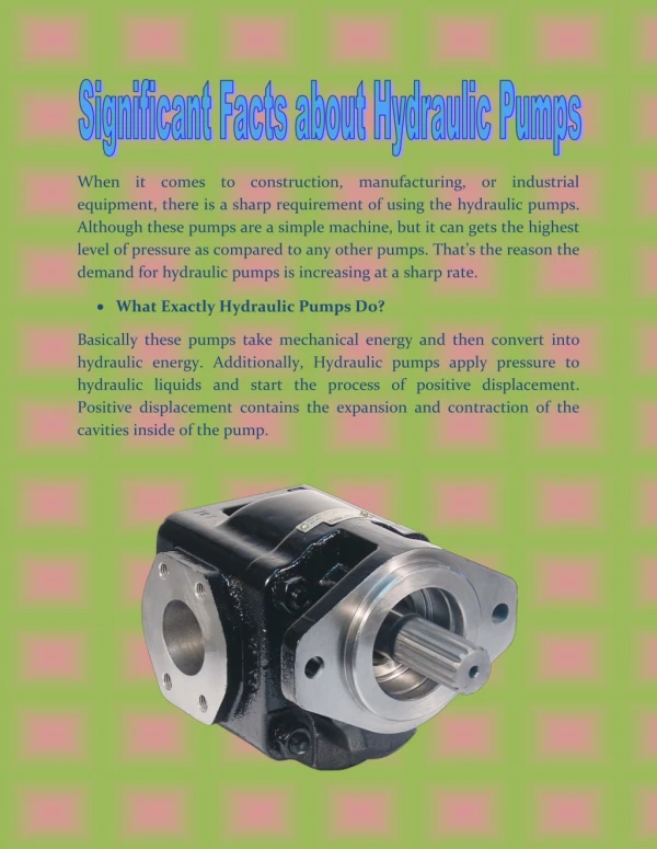
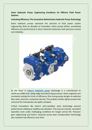
C- Piston pumps A piston pump works on the principle that a reciprocating piston can draw in fluid when it retracts in a cylinder bore and discharge it when it extends. They are mainly used in systems which need pressure of 140 bar and above. It used in high efficiency at high pressure which is important when a constant flow is required independent of pressure variations.
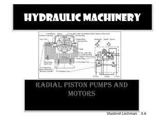
Piston pump mainly divided into two main types, axial design which having pistons that are parallel to the axis of the cylinder block. Axial design have three kinds, 1- bent axis pump. 2- swash plate pump. The second type is the radial design, which has pistons arranged radially in a cylinder block.
Piston pumps Axial Piston Pump Radial Piston Pump Swash Plate Pump Bent Axis Pump
A- Axial piston pump these consists of a number of pistons which are caused to reciprocate by the relative rotation of an inclined plate or by angling the piston block. 1- Bent axis design 1- Bent axis piston Pumps have a rotating cylinder containing parallel pistons arranged radially around the cylinder centre line. 2- The pressure in the fluid causes the pistons to reciprocate over a stroke based on the relative angle of the shaft and cylinder. 3- The motion of the pistons results in the rotation of the shaft.
4- The cylinder is driven by an shaft which is arranged at an angle to the cylinder axis. 5- The shaft includes a flange with a mechanical connection to each piston. 6- The greater the angle of the cylinders to the shaft axes the longer the pistons stroke and the less the rotation speed per unit fluid flow rate.
BENT AXIS PISTON PUMP • Typical displacements to 500 cm3/hr • Typical pressures to 350 bar • No through shaft option (multiple assemblies not possible) • High overall efficiency • Compact package.
2- Swash plate Pump 1- Swash plate pumps have a rotating cylinder containing pistons. 2- A spring pushes the pistons against a stationary swash plate, which sits at an angle to the cylinder. 3- The pistons suck in fluid during half a revolution and push fluid out during the other half. 4- It contains two semi-circular ports. 5- These ports allow the pistons to draw in fluid as they move toward the swash plate (on the backside and not shown here) and discharge it as they move away.
6- For a given speed swash plate pumps can be of fixed displacement like this one, or variable by having a variable swash plate angle.
FIXED AXIAL PISTON PUMP CHARACTERISTICS • Typical displacements to 500 cm3/r • Typical pressures to 350 bar • Multiple assemblies possible • High overall efficiency • Compact package.
VARIABLE DISPLACEMENT PUMP - MAX FLOW Q Q = (No. of Pistons) x (Piston Size) x (Piston Stroke) x (Drive Speed)
VARIABLE DISPLACEMENT PUMP - MAX FLOW STROKE Q Q = (No. of Pistons) x (Piston Size) x (Piston Stroke) x (Drive Speed)
VARIABLE DISPLACEMENT PUMP - REDUCED FLOW STROKE Q Q = (No. of Pistons) x (Piston Size) x (Piston Stroke) x (Drive Speed)
VARIABLE DISPLACEMENT PUMP - REDUCED FLOW STROKE Q Q = (No. of Pistons) x (Piston Size) x (Piston Stroke) x (Drive Speed)
VARIABLE DISPLACEMENT PUMP - ZERO FLOW STROKE Q Q = (No. of Pistons) x (Piston Size) x (Piston Stroke) x (Drive Speed)
VARIABLE DISPLACEMENT PUMP - ZERO FLOW STROKE Q = (No. of Pistons) x (Piston Size) x (Piston Stroke) x (Drive Speed)