Download
1 / 1
10 likes | 30 Vues
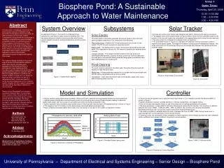
Prototype system using solar energy to clean a pond by circulating water and using a UV sterilizer, managed by a microcontroller. Achieved successful continuous cleaning of the pond. Can be applied to larger pools and fountains.

E N D
Group 3 Demo Times: Thursday, April 23, 2009 10:30-11:00 AM 1:30 – 2:00 PM 3:00 – 4:00 PM System Overview Subsystems Solar Tracker As depicted in Figure 1, the system is comprised of two subsystems: solar electric (gray) and pond cleaning (tan). The two subsystems are united by a microcontroller which directs system operation based on ambient temperature and the position of the sun. Solar Electric • A single axis, active solar tracker was designed and built to improve solar energy conversion. • The stepper motor drive system shown in Figure 2 takes inputs from the controller based on the position of the sun and rotates the solar panel to the appropriate position along the east-west axis. • The drive system is comprised of a stepper motor and gearbox. • The solar panel shown in Figure 3 is oriented at 40 degrees from the horizontal in order to improve solar power uptake. The angle of inclination corresponds to Philadelphia’s latitude, This angle was chosen for the prototype design as an average case between the optimal winter and summer angles. The solar electric subsystem generates and stores power to drive the load bearing system components. It is comprised of the following: Photovoltaic array– A twelve volt,130 watt solar panel was chosen for the system. The PV converts sunlight into electrical current. Battery bank – The battery bank is used to store power generated by the solar panel. It is comprised of two six volt, 190 amp hour sealed solar batteries wired in series. Charge controller – The charge controller prevents the solar array from overcharging the batteries, prevents reverse current flow from the batteries to the solar panel, and prevents battery bank discharge when the batteries have been depleted beyond a certain point. Thermostat Photoresistor Microcontroller Biosphere Pond: A Sustainable Approach to Water Maintenance Solar Tracker Bilge Pump Photovoltaic Array Battery Bank UV Sterilizer Pond Cleaning The pond cleaning subsystem circulates water throughout the pond and kills bacteria to keep the pond clean: Bilge pump – A bilge pump was selected for our system as they are durable and are also easily manipulated with a microcontroller. UV sterilizer – Uses high intensity UV light to kill bacteria, algae, and viruses without harming other pond life. Inverter Charge Controller Figure 2: Solar tracker drive system Figure 1: System block diagram Figure 3: Solar panel Model and Simulation Controller Abstract In recent years, increasingly more focus has been directed towards renewable energy production for the sake of the environment, as well as political and economic stability. Consequently, the goal with this project was to develop a sustainable and environmentally compatible solution to a pressing issue on Penn’s campus. A brief survey of Penn’s facilities led us to the pond in King's Court English House, also known as the Biosphere Pond, which is overcome with algae bloom. The project team sought to develop and implement a solar powered water maintenance system to keep the Biosphere Pond clean. The system’s design is based on the pond’s size as well as historical weather patterns, which were used to simulate power generation for the Biosphere Pond. A prototype has been developed which circulates water throughout the pond and also pumps water through a UV sterilizer, which kills off unsightly bacteria. In addition, the system contains a single-axis sun tracker to improve energy conversion as well as a temperature sensor to prevent operation during freezing temperatures and to maintain system integrity. All of the system’s processes are managed by algorithms installed on a microcontroller. Results for the Biosphere Pond include a successful implementation of a prototype which is able to keep the pond clean on a continuous basis during the spring, summer, and fall seasons. Ultimately, the design process proved that the Biosphere Pond concept is viable and also revealed that the design has the potential for alternative applications including larger pools, fountains, and perhaps even drinking water. Authors John Gillette SSE ‘09 Xiao Ling SSE ‘09 Ravi Patna SSE ‘09 Zachary Zwarenstein SSE ‘09 Advisor Dr. Santiago (ESE) Acknowledgements We would like to thank Professor Santiago, Siddharth Deliwala, MEAM, ESE and King’s Court English House for their help and support over the past year. • Various system configurations were modeled in Microsoft Excel to determine the appropriate battery and solar panel size. • Optimal system configuration and parts were chosen by constructing and solving a linear program seeking to maximize battery bank power over the course of a simulated year while minimizing component costs. • System operation was simulated using fourteen years of historical light intensity data in Philadelphia which is shown in Figure 4. The mapping from UV intensity to solar panel power output was determined empirically. • Figure 5 depicts simulated battery bank power over the course of one year for the system configuration chosen. • Figure 6 shows the system control algorithm which was written in C for intended use with the Motorola 68HC11 shown in Figure 7. • System initialization includes variable definitions, interrupt configuration, and register setting. • Every 30 minutes the program checks to see if the pump and or tracking parameters are satisfied. • The pump parameter is responsible for activating the pump as well as the UV sterilizer. This condition is satisfied between the hours of 8AM – 10AM and 3PM – 5PM. In addition, the condition also requires that ambient temperature be above 38° F to provide a slight buffer above freezing temperatures. • The tracking condition is satisfied when the clock is between the hours of 9AM – 3PM. During these hours, a scanning algorithm is executed every once every 30 minutes. • Following a scan, the solar panel is then realigned to receive maximum solar intensity provided the new orientation yields a sufficient improvement relative to the panel’s current position. Figure 5: Simulated battery bank power Figure 7: 68HC11 Microcontroller Figure 4: Historical UV intensity in Philadelphia Figure 6: Flowchart of Control Algorithm University of Pennsylvania – Department of Electrical and Systems Engineering – Senior Design – Biosphere Pond