Chapter 4: Sheet Metal Forming
Chapter 4: Sheet Metal Forming. 4.4 Folding Edges and Making Seams . Shafizan Bt. Shariffuddin School of Manufacturing Engineering UniMAP. Introduction. Folding sheet metal to form edges and seams of various kinds is one of the most important operations in sheet metal work.

Chapter 4: Sheet Metal Forming
E N D
Presentation Transcript
Chapter 4: Sheet Metal Forming 4.4 Folding Edges and Making Seams Shafizan Bt. Shariffuddin School of Manufacturing Engineering UniMAP
Introduction • Folding sheet metal to form edges and seams of various kinds is one of the most important operations in sheet metal work. • The edges and seams have several purposes:- • to improve the appearance of finished products • to strengthen the work piece • to fasten pieces of metal together
Folding Edges • There are two types of machine commonly used in bending or folding metal to form edges or locks for seams :- • Bar folders • Folding brakes
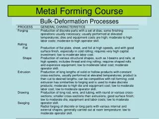
Bar folder • This machine is adapted for bending edges of 22 gage (0.794 mm) metal or lighter. There are six important steps that must be remembered when using the bar folder. • Allowance for the thickness of the metal • Sharpeners of the folded edges • Width of the lock edge • Adjustment for the thickness of metal • Angle of fold • Types of metal
Figure 2 and 3 show some operation that can be performed on bar folder Figure 2: Cross-section view showing bar folder adjusted for sharp fold and for rounded fold. Figure 3: Cross-section view of bar folder showing how to form hemmed edge
Folding Brakes • There are many types of bending brakes used by sheet metal workers. The most widely used machine is the cornice brake. • The average cornice brake has a capacity of 16 gage (1.588 mm) and can also bend the lightest sheet metal.
Edges • Whenever a sheet metal object is made, some type of edges must also be formed. In addition to providing a finish, an edge eliminates the raw edge of the metal that is likely to cut someone and provides additional strength for the edge.
Single Hem • The single hem is a folded edge on the metal made in order to increase its strength and to make a smooth finished edge. • It is one of the most common of all edges since it is the simplest to form. • The hem is folded over in the brake and smashed flat. • The allowance is generally 6 mm. However, on metal heavier than 22 gage, it is common practice to increase the hem to 8 mm to 10mm.
Double hem • The double is a simple single hem done twice. It provides much greater strength than the single hem. • The allowance for a double hem is twice the hem size less 1.5 mm, so that the outside allowance is short and does not cover up the second bend line. Refer Figure 5.
Wired Edge • For a greater amount of strength than that provided by the double hem, the wired edge is used. • This is done by wrapping the sheet metal around a piece of wire. • The allowance added to the pattern depends upon the diameter of the wire. • For 26 gage and lighter, 2½ times the diameter of the wire is added to the pattern. • For 24 gage metal and heavier, allowances must be made for the thickness of the metal in addition to the diameter of the wire.
Seaming • In sheet metal construction, there are a variety of methods for joining the edges of sheet metal. The choice of joint, or seam, is determined primarily by :- • thickness of the metal • the types of metal • the cost of fabrication • the equipment
Types of seams • In planning the fabrication of sheet metal articles, the worker should be able to visualize the type of seam that is best fitted for the specific job. • Various types of seams are diagrammatically shown in Figure 6.
Grooved seam • It is one of the common type of seam used in light or medium gage sheet metal. Figure 7 shows how a grooved seam is formed. Figure 7: Groove seam formed by two “lock” shown at A, hooked together at B, and locked together as in C.
When making a grooved seam, it is necessary to make allowance for the amount of material that is to be added for the lock. The amount depends upon the width of the lock and the thickness of the metal.
The formula for finding the allowance is a follows :- • 24 gage or lighter = 3 x width of lock • 25 gage or heavier = 3 x width of lock plus 5 x thickness of metal • Half of the above allowances are to be added to each side of the pattern. Groove seams are rarely used in metal heavier than 20 gage.
Pittsburgh seam • Sometimes called a hammer lock or hobo lock. It is used as a longitudinal corner seam for variously shaped pipes as the duct. The seam consists of two parts as shown in Figure 8. Figure 8: Pittsburgh seam
The Pittsburgh seam is the most commonly used of any seam in the sheet metal shop. It can be formed on roll-forming machines or on the brake. One of the advantage of this seam is that the single lock can be turned on a curve and the pocket lock can be formed on a flat sheet and then rolled to fit the curve. • The allowance needed for the Pittsburgh seam when formed in the brake is 32 mm. • Figure 9 and 10 show how Pittsburgh seams are made.
Figure 10. Pittsburgh seams may be formed on the brake by the steps shown.
Drive – clip seam • This seam is generally used in connection with S clips for connecting cross seams on duct. The edges vary with job conditions, however, the common width is 13 mm. The actual drive clip is formed as shown in Figure 11.
Figure 11. Drive-clip seams are made by (A) turning edges, (B) forming drive and (C) attaching.
S – clip seam • The S – clip is an S – shaped piece of metal that forms two pocket locks for the joining metal to slip in. Often in covering a wall with sheet metal, the S – clip is bent on the edge of the sheet and is used as shown in Figure 12 and 13.
Figure 12: S-clips are used to join ducts or to sheet metal pieces covering a wall.
Slip – joint seam • This seam is used for a longitudinal corner seam, as shown in Figure 14. It consists of a single lock and double lock. The single lock is slipped into the double lock, completing the assembly of the seam.
Figure 15: Proper and improper joining of slip joint seams in pipe construction.
Double seam • There are two types of double seams. One type is used for making irregular fittings such as square elbows, offsets, boxes, etc. The other type is used to fasten bottoms to cylindrically shaped articles such as pails, tanks, etc. • Both types of seams are shown in the following Figure 16 and 17.
Figure 16: Making a double seam. Figure 17: Making a bottom double seam to fasten cylindrically objects.
Dovetail seam • This seam is an easy and convenient method of joining collars to flanges. There are three types of dovetails :- • Plain dovetails • Beaded dovetails • Flange dovetails