Download
1 / 20
200 likes | 322 Vues
Lightwave Communications Systems Research at the University of Kansas. Objectives and Benefits to Sprint. Development of techniques and identification of tradeoffs for increasing Sprint’s network capacity while maintaining reliability Identifying and evaluating long-range technology trends

E N D
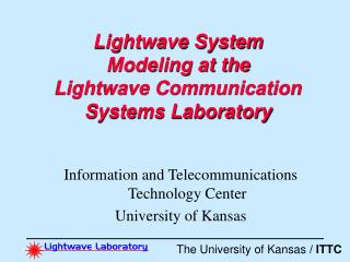
Lightwave Communications Systems Research at the University of Kansas
Objectives and Benefits to Sprint • Development of techniques and identification of tradeoffs for increasing Sprint’s network capacity while maintaining reliability • Identifying and evaluating long-range technology trends • Evaluating the feasibility of new technologies for Sprint’s network • Resource of graduates educated in state of the art lightwave communication systems
Laboratory Infrastructure • Started Jan. ‘96 • 600 ft2 laboratory space • Key test equipment includes • Lucent FT-2000 WDM system • Ciena 16 system • Soliton generator (built at KU) • Recirculating loop (built at KU) • Optical Clock Recovery (built at KU)
Participants • Faculty: Ken Demarest (WDM Systems, modeling) Chris Allen (WDM and coherent systems) Rongqing Hui (WDM systems, devices) Victor Frost (ATM, SONET, networking) • Postdoctoral Fellows: • 1 • Students: 6 Graduate, 3 undergraduate
Major Results and Technology Transfer • 1 Patent and 2 patent applications • 11 Papers in major photonics journals • Development of soliton generator and circulating loop testbed • WDM modeling software and measurements • PMD compensation and measurement techniques • Subcarrier modulation
Current Activities • WDM Modeling/measurements • Subcarrier modulation • PMD compensation • Link quality monitoring
All-Optical Clock Recovery • Goal: To make optical networks optically transparent by performing clock recovery without electronics • What we accomplished • Developed an all-optical clock recovery device compatible with WDM • Patent application
Downshifts frequency (ƒseed) Data signal in Clock signal out 80 20 10.9 GHz Mod Isolator ƒ ƒ ƒdata ƒstokes ƒdata Fiber Interaction of data and index grating produce cw propagating stokes Index grating produced by data filters the clock from the seed. ƒ ƒ ƒdata ƒseed ƒphonon Stokes wave generated by interaction of data and index grating provides amplification ƒstokes ƒdata ƒ ƒdata ƒclock All-Optical ClockRecovery Using SBS
WDM Clock Recovery Input Output =1.557 m 10 Gbps 27-1 prbs =1.556 m 100 ps/div
Modeling and Measurements • Goal: • Model fiber link and network performance for dense wavelength division multiplexed operation • What we’ve done • Developed high fidelity model for fiber transport • Applied model to address WDM over DSF issues raised by Sprint • What we’re doing • Increasing the capabilities of this model to handle hundreds of optical channels simultaneously. • Modeling legacy network performance at 40 Gb/s
120 km 120 km 120 km 120 km 120 km System 1 Tx Rx SMF SMF SMF SMF SMF 120 km 120 km 120 km 120 km 120 km System 2 Tx Rx DSF DSF SMF SMF SMF NEC WDM System on DSF/SMF Two OC-48, WDM system configurations • Dispersion: SMF: ~ 16 ps/km-nm, DSF: ~ 0 ps/km-nm • Expectations: System 2 has better performance (less dispersion) • Reality: System 1: error free, System 2: mass errors
NEC WDM System on DSF/SMF • What we found: Strong cross phase modulation (XPM ) in the DSF caused spectral broadening High dispersion in the SMF caused pulse-width broadening
NEC WDM System on DSF/SMF Bandwidth Expanding Factors in DSF and SMF 1.45 1.4 DSF Spectral expanding factor for100 km DSF and 100 km SMF 1.35 1.3 1.25 Bandwidth Expanding Factor 1.2 1.15 SMF 1.1 1.05 1 0 10 20 30 40 50 60 70 80 90 100 Distance (km) Calculated eye-diagrams Bit Rate: 2.5 Gb/s Channel Number: 4 Number of Samples/bit: 64 Channel Wavelength: 1553.50 nm Bit Rate: 2.5 Gb/s Channel Number: 4 Number of Samples/bit: 64 Channel Wavelength: 1553.50 nm 30 30 25 System 2 25 System 1 20 Pulse intensity (mW) 20 Pulse intensity (mW) 15 15 10 10 5 5 0 0 100 200 300 400 500 600 700 800
Subcarrier Modulation Techniques • Goal: • Increase fiber link capacity and flexibility by multiplexing several digital signals on a single optical carrier • What we’ve done • Modeled optical subcarrier modulation systems • Constructed and tested a 2-channel system • What we’re planning to do • Construct and test a 4-channel system • Determine the commercial feasibility of optical subcarrier systems for digital applications on long links.
optical carrier ch2 ch1 Optical single-sideband technique Advantage of optical SSB: 1. Better bandwidth utilization 2. Possibility of moving dispersion compensation to electronics domain
PMD Compensation • Goal • Increase fiber link data rates by reducing the effects of polarization mode dispersion (PMD) • What we’ve done • Developed a scheme for compensating first order PMD • Demonstrated a prototype • What we’re planning to do • Measure the PMD on a Lawrence-K.C. link • Test our compensation scheme on this link
Current Thrusts • PMD Compensation • Dense WDM modeling • Subcarrier modulation