Download
1 / 40
400 likes | 408 Vues
Explore the structural design concepts and elements re-engineered for the Innovation Building in College Township. This senior thesis project revamps the foundation, lateral systems, and redesigns the overall structure for optimal functionality and efficiency.

E N D
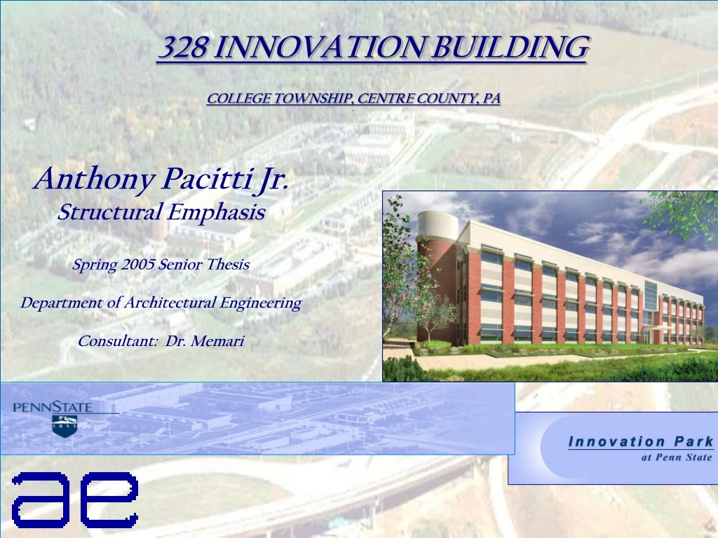
328 INNOVATION BUILDING • COLLEGE TOWNSHIP, CENTRE COUNTY, PA • ` Anthony Pacitti Jr. Structural Emphasis Spring 2005 Senior Thesis Department of Architectural Engineering Consultant: Dr. Memari
Primary Project Team Owner of Record: RMP Co. Development Of Record : Innovation Capital Partners, LP Architect : Robert L. Kimball & Associates Engineer: Robert L. Kimball & Associates General Contractor : Poole Anderson MEP : Subcontracted by Poole Anderson
Existing Conditions • Location: • College Township, Centre County, Pennsylvania • Cost: • $10.1 Million for all onsite work, including tenant fit up allowances of $9.80 per rentable square foot • Size: • 3 stories with 73,943 sq. ft of tenant space • Functions: • Research and Development 10,000 sq. ft • Laboratories 20,000 sq. ft • Corporate Office Space 43,943 sq. ft • Project Delivery Method: • Negotiated firm price with a General Contactor, including a share of cost savings, provided the cost is lower than an established bench mark.
Existing Floor System Typical Bay Consists of: • 3-W16 X 26 Interior Beams • 2- W24 x 26 Girders • 1- W16 x 26 , 1- W18 x 40 Connecting Into Columns • 3 inch Slab + 3 inch Deck Figure 2--Typical bay (30’-0” -39’-0”)
K Joist Roof System 22 K 4 Joists supported by W24 x 68 Girder W16 x 26 Exterior Beam 1-1/2” 20 Gauge Type B Deck 2 W 24 x 55 Beams Were Added to Support the VAV Mechanical Systems Existing Roof Structure Typical Bay of Roof
Existing Foundation • Square Footing and Strip Footing • Square Footings Ranging in size from 3’-0” x 3’-0” to 12’-0” x 12’-0” • Strip Footing Ranging in size from 1’-2” to 2’-0” Existing Foundation Plan
Existing Lateral System • 6 Braced Frames • 4-North/South Direction • 2-West/East Direction • Seismic Controls • Typical Frames Are Composed of : • 2-W 10 Columns • Variety of W12, W16, W21, W24 and HSS Compression and Tension Members Existing Lateral System
Redesigned Building Outline • Structural System • Flat Plate System without beams • Floor system • Columns • Shear Walls • Construction Schedule • Rescheduled for Concrete System • Electrical System • Resize Main Distribution Panel • Resize BUS-DUCT to Each Floor and In the Main Distribution Panel • Resize Breakers
Goals for New Design • Direct Effect on the Schedule • Lower Overall Cost • More tenant Space with the Additional 2 Stories • Increase Floor to Floor Height
Redesigned Building Size • 5-Story Building • Total Height = 75’-0” • 14’-0’ Floor to Floor Height • Additional 50,000 sq. ft of Floor Area
Design Loads • DEAD LOAD = 165 PSF (12”/12)(150PSF)+(15PSF)FLOORING • LIVE LOAD = 80 PSF • Fy = 60,000 PSI • F’c = 4,000 PSI
Direct Design Criteria • MINIMUM OF THREE CONTINUOUS SPANS IN EACH DIRECTION • LONG-SPAN/ SHORT-SPAN RATIO NOT GREATER THAN 2 • SUCCESSIVE SPAN LENGTHS IN EACH DIRECTION SHALL NOT DIFFER BY MORE THAN ONE 1/3 THE LONGER SPAN • ALL LOADS MUST BE DUE TO GRAVITY ONLY • SERVICE LIVE LOAD SHALL EXCEED TWO TIMES THE SERVICE DEAD LOAD
Flat Plate System • Slab Thickness • ACI 9.5c -Table 13-1 • 12” slab • Computing the Static Moment • Exterior Panel • Negative Moment at the exterior end of the end span = 0.26Mo • Positive Moment in the end span = 0.52 Mo • Negative Moment at the Interior end of the end span = 0.70 Mo • Interior Panel • Negative Moment = -0.65 Mo • Positive Moment = 0.35Mo
Design of Reinforcement of Moment Transferred By Flexure • Exterior Column • 58”effective width • 7 of the column strip bars and adding 6 #6 bars in the region • Interior Column • Reinforcement in the slab was sufficient
Deflection • INTERIOR PANEL • DEAD LOAD =150 +50 =165 PSF • SERVICE LOAD = 165 + 80 = 245 PSF • CONSTRUCTION LOAD = 2*150 = 300 PSF CONTROLS
Deflection • Average deflection of the mid-spans of the column strips in one direction added to the mid-span deflection of the perpendicular middle strip. • Final deflection = 0.327 < l/360 and l/480.
Columns • EXTERIOR COLUMN (FOR ALL FLOORS) • 22” X 22” • 4 #10 BAR • # TIES @ 18” • LAP SPLICE = 38” • INTERIOR COLUMN (FOR ALL FLOORS) • 22” X 22” • 12 #10 BAR • # TIES @ 18” • LAP SPLICE = 38 “
Wind Wind Speed = 90 Exposure B Frequency = 3.07 Pressure = 12 psf Seismic Site Classification B Category 3 (Occupancy) Group 1 Cs = 0.04 T = .484 seconds Lateral System Design Loads
Lateral System Design Loads SEISMIC – CONTROLLING FACTOR
Shear Wall Design • Wall Thickness • 12” • 25’ Length • 17 # 5 bars @ 18 o.c. Vertical Reinforcement • #4 at 12”o.c Horizontal Reinforcement
Existing Electrical Riser Diagram 1600 AMP BREAKER
Existing Electrical Riser Diagram 1600 AMP BREAKER 1600 AMP BUS DUCT
Existing Electrical Riser Diagram 1600 AMP BREAKER 1600 BUS DUCT 1500 AMP BREAKER
Existing Electrical Riser Diagram 1600 AMP BREAKER 1600 AMP BUS DUCT 1500 AMP BREAKER 1000 AMP Plug-In Bus Way / CABLE TAP CAP
New Electrical Riser Diagram 2500 AMP BREAKER 2500 AMP 2500 AMP BUS DUCT 1500 AMP 1600 AMP cap 1600 AMP BUSDUCT-480/277
New Electrical Riser Diagram 2500 AMP BREAKER 2500 AMP 2500 AMP BUS DUCT 1500 AMP 1600 AMP cap 1600 AMP BUSDUCT-480/277 2500 AMP BUS DUCT
New Electrical Riser Diagram 2500 AMP BREAKER 2500 AMP 2500 AMP BUS DUCT 1500 AMP 1600 AMP cap 1600 AMP BUSDUCT-480/277 2500 AMP BUS DUCT 1500 AMP BREAKER
New Electrical Riser Diagram 2500 AMP BREAKER 2500 AMP 2500 AMP BUS DUCT 1500 AMP 1600 AMP cap 1600 AMP BUSDUCT-480/277 2500 AMP BUS DUCT 1500 AMP BREAKER 1600 AMP Plug-In Bus Way
New Electrical Riser Diagram 2500 AMP BREAKER 2500 AMP 2500 AMP BUS DUCT 1500 AMP 1600 AMP cap 1600 AMP BUSDUCT-480/277 2500 AMP BUS DUCT 1500 AMP BREAKER 1600 AMP Plug In Bus Way ADDITIONAL FLOORS
Conclusion • Flat Plate System • Longer Schedule • More Columns • Steel System = More Sufficient
THANK YOU • ROBERT L. KIMBALL & ASSOCIATES • DON SMITH • CHRIS BOWERS • MATT MURPHY • RMP Co. • ALL AE DEPARTMENT FACULTY • FRIENDS AND FAMILY