Download
1 / 21
210 likes | 350 Vues
12: Electromagnetic Induction. 12.1 Induced Electromotive Force. Induced EMF Revision of magnetism: Magnetic flux: The amount of field or number of field lines passing through a certain area. Measured in Webers ( Wb ).

E N D
12: Electromagnetic Induction 12.1 Induced Electromotive Force
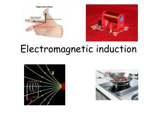
Induced EMF • Revision of magnetism: • Magnetic flux: The amount of field or number of field lines passing through a certain area. Measured in Webers (Wb). • Magnetic flux density: The amount of magnetic flux per unit cross sectional area perpendicular to a field. Measured in Tesla (T). • Force on a current carrying conductor in a magnetic field: F = BIL • Force on a single moving charge in a magnetic field: • F = Bqv(from the above, if v = L / t)
Moving a conductor through a B field Consider a conductor of length L moving through a magnetic field (strength B) at speed v. The electron is moving ‘down’ (so it effectively forms a current moving ‘up’). Fleming’s LHR tells us that the force on the electron is to the left. As a result of movement of electrons, opposite charges build up at either end of the conductor. x xxx x xxx v B e L
The charges in turn create a p.d. across the wire and thus an electric field. The field will exert electric force on remaining free electrons, balancing out the magnetic force, so they don’t move. so... FB = FE but we know... FB = Bqv = Bev (e = electron charge) and also... Equating gives... Rearrange to give... E = (-) ΔV = V FE = Eq = eV Δx L L Bev = eV L V = (-) BLv
This gives the EMF induced across a single wire moving perpendicular to a uniform magnetic field. However if the motion is at an angle of less than 90° to the field then we only use the component of the field perpendicular to the motion... This voltage supplies an EMF (ε) to an external circuit. So... ε = EMF generated across wire (V) B = magnetic flux density (Tesla) L = length of conductor in field (m) v = velocity of moving conductor (ms-1) ε=BLv v B θ ε= B sinθLv
Magnetic Flux and Magnetic Flux Linkage In simple terms a ‘single flux’ can be thought of as a single magnetic field line. If magnetic flux density (B) is the flux (ϕ) per unit cross sectional area perpendicular to the field then... Magnetic flux density = Magnetic flux Area B = ϕ A ϕ = Magnetic flux (Wb or Tm2) B = Magnetic flux density (T) A = Area (m2) ϕ = BA
If a single flux passes through a coil, the coil is ‘linked’ to the flux (or ‘threaded’ by the flux). We could say there is magnetic flux linkage of 1. If the coil is linked (‘threaded’) by two flux then the flux linkage is 2 and so on. Increasing the number of coils also increases the flux linkage. E.g. If a solenoid has three coils linked by two flux then the flux linkage is six. Note: Even a straight wire has flux linkage although this is less easy to define. N=1 for a straight wire. Total magnetic flux linkage = Nϕ
E.g. A small circular coil of area 7.5 x 10⁻³ m2 contains 400 turns of wire. If it is linked by a perpendicular magnetic field of flux density 5.0 x 10⁻² T, determine the magnetic flux linkage through the coil. Answer: Flux linkage = N ϕ and ϕ = BA So... Flux linkage = NBA = 400 x (5.0 x 10-2) x (7.5 x 10–3) = 0.15 Wb
Faraday’s law Michael Faraday discovered electromagnetic induction in 1831. Faraday’s law states... so... Note: Negative sign is a result of Lenz’s law. The induced EMF in a circuit is equal to the rate of change of flux linkage in a circuit. ε = - dNϕ dt
Lenz’s Law Demo: A north pole moving into a coil creates north pole, resisting its motion. A north pole moving out of a coil creates a south pole, resisting its motion.
The magnitude of an induced EMF is given by Faraday’s Law. However the direction of an induced current can be determined by applying Lenz’s law which states... In the previous example, if the currents were induced in the opposite direction the magnet would be repelled – free energy! Impossible. So Lenz’s Law is an application of the principle of conservation of energy. The direction of an induced current is always such as to oppose the change that causes it.
Demo: • Neodymium magnet in copper tube. • Swinging aluminium vane in magnetic field.
Conclusion:Explain the shape of this graph in as much detail as possible.
Flux through coil is changing so EMF induced. • Rate of change of flux is increasing as magnet speeds up so EMF is increasing. • When magnet in central position there is no change in flux so EMF is zero for an instant. • As magnet exits, Lenz’s law tells us that the current must flow in the opposite direction so as to oppose motion. reversed EMF • Max induced EMF occurs on exit because magnet is moving fastest. • t2 is smaller due to greater speed.
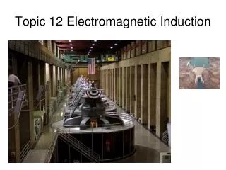
Electromagnetic Induction Braking • Induced currents are used in electromagnetic induction braking in vehicles: • An electromagnet is switched on next to the rotating non-magnetic metal disk. • The disk cuts through the B field, inducing EMFs and currents within the disk. • Currents flow between the edge and centre of disk. Energy is then lost as heat or the EMF can be used to charge batteries.
Subtitle Text
Subtitle Text
Subtitle Text
Subtitle Text
Subtitle Text