Full Duplex Transceiver Module Development Project
This project focuses on designing, building, and testing a full duplex TxRx module with optional second run. It includes circuit schematic, layout, alignment tolerance analysis, and component ordering. The project also involves developing a Gigabit Receiver Board with power passives and a limiting amplifier for signal conversion. The aim is to optimize the module for high-speed data communication.

Full Duplex Transceiver Module Development Project
E N D
Presentation Transcript
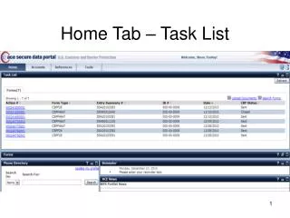
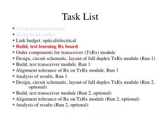
Task List Group management plan Background studies Link budget: optical/electrical Build, test learning Rx board Order components for transceiver (TxRx) module Design, circuit schematic, layout of full duplex TxRx module (Run 1) Build, test transceiver module, Run 1 Alignment tolerance of Rx on TxRx module, Run 1 Analysis of results, Run 1 Design, circuit schematic, layout of full duplex TxRx module (Run 2, optional) Build, test transceiver module (Run 2, optional) Alignment tolerance of Rx on TxRx module (Run 2, optional) Analysis of results (Run 2, optional)
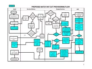
Gigabit Receiver Board Power passives Light Signal CML (Current mode logic) ECE 4006 Limiting Amp TIA
Receiver components • TIA (transimpedance Amplifier) • Amplifies small PD (photodiode) current • Low noise • Low input impedance (~600 Ohms) • Converts current to voltage • Limiting Amplifier • Boosts TIA output voltage 30mV to >100mV • Converts analog to “digital” (limiting) CML
On Board Passives Supply Decoupling DC Bias AC coupling AC coupling AC coupling Input Impedance Match Supply Decoupling
Board Layout J2 J1 J3 • Short lines • 45 degree angles