Download
1 / 16
160 likes | 352 Vues
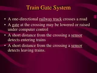
Real Time Systems: Train Gate System II. Chieu Wang Vincent Ng. Current System. A unidirectional railway track that crosses a one way road. A single gate at the crossing which may be lowered or raised under the control of a computer.

E N D
Real Time Systems:Train Gate System II Chieu Wang Vincent Ng
Current System • A unidirectional railway track that crosses a one way road. • A single gate at the crossing which may be lowered or raised under the control of a computer. • There are two sensors present to detect incoming and outgoing trains.
Current System Entry Sensor Exit Sensor Gate
Processes • Se – represents the entry sensor. • Sl – represents the exit sensor. • G – represents the gate. • M – the monitor that keeps track of the number of trains in the area. • C – controls the gate.
Se Sl G C Train Gate CRSM Communication Diagram tr trout trin gok og cg M cont_og cont_cg
Proposed Modifications • Change to a two track unidirectional railway that crosses over a two way road. • Model will include two gates at the crossing which may be lowered or raised that is under the control of a computer.
Proposed Modifications, Con’t • There will be four sensors in the system: • Two sensors for each track to detect incoming and outgoing trains.
Train Gate System II Entry Sensor 2 Gate 2 Exit Sensor 2 Entry Sensor Gate 1 Exit Sensor
Details of Proposed Modifications • Se2 – represents the entry sensor on second track. • Sl2 – represents the exit sensor on second track. • G2 – represents the second gate.
SE2 SE1 SL1 G1 M C SL2 G2 Train Gate II CRSM Communication Diagram tr gok trin tr 2 trout og cg trin 2 cont_og2 cont_cg2 cg 2 og2 cont_og trout 2 cont_cg gok2
Train Sensore Monitor Controller Gate Sensorl Sensore1 Sensore2 Sensorl1 Sensorl2 Gate1 Gate2 Recommended Implementation and Modeling
Train SE1 SE2 M C G1 G2 SL1 SL2 Simplified Modeling Version
Advantages • Existing classes does not need to be modified. • ie. sensore.java, sensorl.java, gate.java • Existing classes are easily cloned for reuse. • Existing timing constraints can be applied to the new classes.
Disadvantages • The monitor and controller process require substantial modifications to handle the new classes. • Issues with sequence of processing.
Difficulties Encountered • The monitor and controller class required major overhaul to accommodate multiple events that may occur at the same time.
Conclusion • The modified system will provide a more realistic model of a train gate system. • By incorporating multiple tracks and sensors, the model will further reinforce the basic concepts of concurrency and synchronization among processes