Network Layer and Circuit Switching
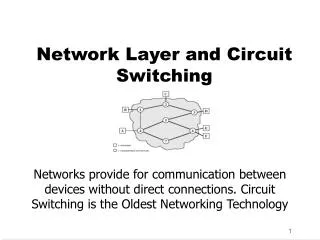
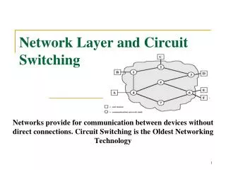
Network Layer and Circuit Switching. Networks provide for communication between devices without direct connections. Circuit Switching is the Oldest Networking Technology. Why Networks?. Why we need networks? When point to point link or multipoint link is not available between devices

Network Layer and Circuit Switching
E N D
Presentation Transcript
Network Layer and Circuit Switching Networks provide for communication between devices without direct connections. Circuit Switching is the Oldest Networking Technology
Why Networks? • Why we need networks? • When point to point link or multipoint link is not available between devices • Why we can’t connect devices directly? This is obvious for two reasons: • The direct connection of every device with every other device would require N(N-1) full duplex links • This would be prohibitively expensive • Each communication link would require a port on the device. • The cost of the ports would be a limiting factor and also their physical size.
Kinds of Networks • By Communication Technique • Switched Networks • Broadcast Networks e.g. LANs • By Geographical Coverage • Wide Area Network • Cover large geographical areas, often crossing public right-of-ways • Usually consist of several interconnected switching points • Local Area Network • Small scope, usually a building or cluster • Typically owned by the same organization that owns the equipment
Switched Network Types • Long distance transmission is typically done over a network of switched nodes • Nodes not concerned with content of data • End devices are stations • Computer, terminal, phone, etc. • A collection of nodes and connections is a communications network • Data routed by being switched from node to node • Nodes may connect to other nodes only, or to stations and other nodes
Switched Network Types • Node to node links usually multiplexed • Two types of switched networks • Circuit Switched Networks • Packet Switched Networks
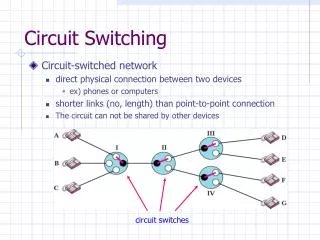
Circuit-Switching • Definition: Communication in which a dedicated communications path is established between two devices through one or more intermediate switching nodes • Oldest Networking Technology - more than a hundred years old • Dominant in both voice and data communications today • e.g. PSTN is a circuit-switched network • Relatively inefficient (100% dedication even without 100% utilization)
Circuit-Switching • Dedicated communication path between two stations • Three phases • Establish • Transfer • Disconnect • Must have switching capacity and channel capacity to establish connection • Must have intelligence to work out routing
Circuit Switching - Disadvantages • Inefficient • Channel capacity dedicated for duration of connection • If no data, capacity wasted • Set up (connection) takes time • Once connected, transfer is transparent • Developed for voice traffic (phone)
Circuit-Switching Stages • Circuit establishment • Station requests connection from node • Node determines best route, sends message to next link • Each subsequent node continues the establishment of a path • Once nodes have established connection, test message is sent to determine if receiver is ready/able to accept message • Transfer of information • Point-to-point transfer from source to node • Internal switching and multiplexed transfer from node to node • Point-to-point transfer from node to receiver • Usually a full-duplex connection throughout
Circuit-Switching Stages • Circuit disconnect • When transfer is complete, one station initiates termination • Signals must be propagated to all nodes used in transit in order to free up resources
Circuit Switching Application • Circuit switching is well suited for analog voice communications as in the telephone network. • In-efficient for data networks due to its resource allocation nature • Ill-suited to data communication because data traffic is BAD
Examples of Circuit Switching • Public Switched Telephone Network - PSTN • Private Automatic Branch Exchange - PABX • Integrated Services Digital Network - ISDN
Public Switched Telephone Network (PSTN) • PSTN (Public Switched Telephone Network), refers to the international telephone system based on copper wires carrying analog voice • Telephone service carried by the PSTN is often called plain old telephone service (POTS).
Subscribers Local loop Connects subscriber to local telco exchange Exchanges Telco switching centers Also known as end office >19,000 in US Trunks Connections between exchanges Carry multiple voice circuits using FDM or synchronous TDM Managed by IXCs (inter-exchange carriers) Public Switched Telephone Network (PSTN) Elements
Circuit Switching Node:Digital Switch • Provides transparent signal path between any pair of attached devices • Typically full-duplex
Circuit-Switching Node:Network Interface • Provides hardware and functions to connect digital devices to switch • Analog devices can be connected if interface includes CODEC functions • Typically full-duplex
Circuit-Switching Node:Control Unit • Control Unit • Establish connections • Generally on demand • Handle and acknowledge requests • Determine if destination is free • construct path • Maintain connection -while needed • Disconnect - Breaks down connection on completion
Blocking or Non-blocking • Blocking • A network is unable to connect stations because all paths are in use • A blocking network allows this • Used on voice systems • Short duration calls • Non-blocking • Permits all stations to connect (in pairs) at once • Used for some data connections
Space-Division Switching Developed for analog environment, but has been carried over into digital communication Requires separate physical paths for each signal connection Uses metallic or semiconductor “gates” Time-Division Switching Used in digital transmission Utilizes multiplexing to place all signals onto a common transmission path Bus must have higher data rate than individual I/O lines Switching Techniques
Circuit Switch Design - Cross Bar Switch • Crossbar switch • Number of crosspoints grows as square of number of stations • Loss of crosspoint prevents connection • Inefficient use of crosspoints • All stations connected, only a few crosspoints in use • Non-blocking
Cross Bar Switch • A cross bar switch connects n inputs to m outputs in a grid, using electronic micro switches (transistors) at each crosspoint. • The major limitation of this design is the number of crosspoints required. • To connect n inputs to m outputs using a crossbar switch requires nxm crosspoints. • E.g to connect 1000 inputs to 1000 outputs requires a switch with 1,000,000 crosspoints • A crossbar with this number of crosspoints is impractical. • Such a switch is also inefficient because only fewer than 25% of the crosspoints are in use at any given time.
Multistage Switch • Reduced number of crosspoints • More than one path through network • Increased reliability • More complex control • May be blocking
Multistage Switch • To design a three-stage switch, we follow these steps: • We divide the N input lines into groups, each of n lines. For each group, we use one crossbar of size nxk, where k is the number of crossbars in the middle stage. In other words, the first stage has N/n crossbars of nxkcrosspoints • We use k crossbars, each of size (N/n) x (N/n) in the middle stage • We use N/n crossbars, each of size kxn at the third stage
N/n(nxk) + k(N/n x N/n) + N/n(k x n) = In a three-stage switch, the total number of crosspoints is 2kN + k(N/n)2 which is much smaller than the number of crosspoints in a single-stage switch (N2).
Example 8.3Design a three-stage, 200 × 200 switch (N = 200) with k = 4 and n = 20. Solution In the first stage we have N/n or 10 crossbars, each of size 20 × 4. In the second stage, we have 4 crossbars, each of size 10 × 10. In the third stage, we have 10 crossbars, each of size 4 × 20. The total number of crosspoints is 2kN + k(N/n)2, or 2000 crosspoints. This is 5 percent of the number of crosspoints in a single-stage switch (200 × 200 = 40,000).
Clos criterion • Clos investigated the condition of nonblocking in multistage switches and came up with the following formula • In a nonblocking switch, the number of middle-stage switches must be at least 2n-1. In other words, we need to have k > 2n-1 • According to the Clos criterion: n = (N/2)1/2 k > 2n – 1 Crosspoints ≥ 4N [(2N)1/2 – 1]
Example 8.4 Redesign the previous three-stage, 200 × 200 switch, using the Clos criteria with a minimum number of crosspoints. Solution We let n = (200/2)1/2, or n = 10. We calculate k = 2n − 1 = 19. In the first stage, we have 200/10, or 20, crossbars, each with 10 × 19 crosspoints. In the second stage, we have 19 crossbars, each with 10 × 10 crosspoints. In the third stage, we have 20 crossbars each with 19 × 10 crosspoints. The total number of crosspoints is 20(10 × 19) + 19(10 × 10) + 20(19 ×10) = 9500.
Circuit Switch Design - TDM Bus Switch • Partition low speed bit stream into pieces that share higher speed stream • e.g. TDM bus switching • based on synchronous time division multiplexing • Each station connects through controlled gates to high speed bus • Time slot allows small amount of data onto bus • Another line’s gate is enabled for output at the same time
Issues in Circuit Switched Networks • Routing • Control Signalling
Routing • Routing in the network tries to determine the path from a given source to a given destination • Many connections will need paths through more than one switch • Need to find a route • Efficiency • Resilience • Public telephone switches are a tree structure • Static routing uses the same approach all the time • Dynamic routing allows for changes in routing depending on traffic • Uses a peer structure for nodes
Routing in Circuit-Switched Networks • Requires balancing, efficiency and resiliency • Traditional circuit-switched model is hierarchical, sometimes supplemented with peer-to-peer trunks • Newer circuit-switched networks are dynamically routed: all nodes are peer-to-peer, making routing more complex - almost like packet switching
Static Hierarchical Routing • Tracing up the tree to the first common node, and then tracing down the tree to the called subscriber • Resiliency to the network, additional high usage trunks were added that cut across the tree structure to connect exchanges. • Minimum switching costs, flexibility only via alternate trunks • Not able to adapt to changing conditions • Typically in such designs the result of a failure is a major local congestion near the site of the failure
Alternate Routing • A dynamic routing approach is one in which routing decisions are influenced by current traffic conditions • In Alternate routing schemes the possible routes between two end offices are predefined • Originating switch selects the best route for each call • Routes listed in preference order • Different sets of routes may be used at different times • Routing paths can be fixed (1 route) or dynamic (multiple routes, selected based on current and historical traffic)
Alternate Routing • A form of the dynamic alternate routing technique is employed by the Bell Operating Companies for providing local and regional telephone service, referred as multialternate routing (MAR) • This approach also used in AT&T in its long distance network which is referred as dynamic non-hierarchal routing (DNHR)
Adaptive Routing • Traffic reporting and analysis with new paths computed periodically, adapts to net load, events • Need to use algorithms to determine paths dynamically, based on load/congestion vectors
Control Signaling • Manage the establishment, maintenance, and termination of signal paths • Includes signaling from subscriber to network, and signals within network • In-channel Control Signalling • In-channel signaling uses the same channel for control signals and calls • Common Channel Control Signalling • Common-channel signaling uses independent channels for control (SS7)
Control Signaling Functions • Audible communication with subscriber • Transmission of dialed number • Call can not be completed indication • Call ended indication • Signal to ring phone • Billing info • Equipment and trunk status info • Diagnostic info • Control of specialist equipment
Control Signal Sequence • Both phones on hook • Subscriber lifts receiver (off hook) • End office switch signaled • Switch responds with dial tone • Caller dials number • If target not busy, send ringer signal to target subscriber • Feedback to caller • Ringing tone, engaged tone, unobtainable • Target accepts call by lifting receiver • Switch terminates ringing signal and ringing tone • Switch establishes connection • Connection release when Source subscriber hangs up
Switch to Switch Signaling • Subscribers connected to different switches • Originating switch seizes interswitch trunk • Send off hook signal on trunk, requesting digit register at target switch (for address) • Terminating switch sends off hook followed by on hook (wink) to show register ready • Originating switch sends address
Location of Signaling • Subscriber to network • Depends on subscriber device and switch • Within network • Management of subscriber calls and network • More complex • SS7
In Channel Signaling • Use same channel for signaling and call • Requires no additional transmission facilities • Inband • Uses same frequencies as voice signal • Can go anywhere a voice signal can • Impossible to set up a call on a faulty speech path • Out of band • Voice signals do not use full 4kHz bandwidth • Narrow signal band within 4kHz used for control • Can be sent whether or not voice signals are present • Need extra electronics • Slower signal rate (narrow bandwidth)
Drawbacks of In Channel Signaling • Limited transfer rate • Delay between entering address (dialing) and connection • Overcome by use of common channel signaling