MICROPROCESSOR BASED SYSTEM DESIGN
MICROPROCESSOR BASED SYSTEM DESIGN. Lecture # 17 - 18. BY PROF. DR. B. S. CHOWDHRY. Input and output interfaces. Hardware Interfaces are required to enable input and output of data to and from a computer. Various I/O techniques exist. Direct Transfer Test and Transfer Interrupt Transfer


MICROPROCESSOR BASED SYSTEM DESIGN
E N D
Presentation Transcript
MICROPROCESSOR BASED SYSTEM DESIGN Lecture # 17 - 18 BY PROF. DR. B. S. CHOWDHRY
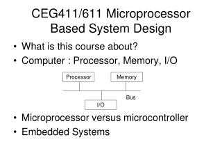
Input and output interfaces • Hardware Interfaces are required to enable input and output of data to and from a computer. • Various I/O techniques exist. • Direct Transfer • Test and Transfer • Interrupt Transfer • Direct Memory Access • Facilities provided by typical microprocessor chips. • How to design interfaces for computers and microprocessor systems. • The Intel family of microprocessors are no different from
Characteristics of I/O Devices • The more complex devices may well require much more complex interfaces than simple devices such as switches and lamps. • Microprocessors are generally connected to a much wider range of devices than larger computers because their range of application is much wider.
ISOLATED INPUT AND OUTPUT • In Isolated input & output, the data transfer between microprocessor and the I/O device takes places using special I/O instructions IN and OUT. • In memory-mapped I/O, and instruction that references to memory can accomplish the I/O transfer. • The Isolated I/O (I/O via separate address space) is the most common I/O transfer technique used in Intel Microprocessor Based System. • The term ISOLATED describes how the I/O locations are isolated from the memory system in a separate I/O address space.
ISOLATED INPUT AND OUTPUT (Contt..) • The address for Isolated I/O devices are called PORTS. It is separate from the memory. • The user can expand the memory to its full size without using any of this space for I/O devices. • DISADVANTAGE of ISOLATED I/O: • The data transfer between I/O & microprocessor must be accessed by INS, OUT, OUTS instructions. • Separate Control Signals for I/O space are used (using M/IO & W/R) that indicate an I/O read (IORC) or an I/O write (IOWC) operation.
ISOLATED INPUT AND OUTPUT (Contt..) • In PC, Isolated I/O ports are used for controlling peripheral devices. • 8-bits port address is used to access devices located on the system board, such as: Timer, Keyboard Interface. • 16-bits port address is used to access serial & parallel port. Video (CGA/VGA) & Disk Drive System. • DISADVANTAGE of MEMORY-MAPPED I/O: The portion of the memory system is used to as the I/O map. This reduces the amount of memory available to applications.
Input & Output MAP of PC • The PC used part of I/O map for DEDICATED APPLICATIONS. • The I/O space between ports 0000H and 03FF is normally reserved for Computer System. • The I/O ports located at 0400H-FFFFH are generally available for user applications.
I/O INSTRUCTIONS • Both IN & OUT instructions transfer data between I/O device & microprocessor’s accumulator (AL, AX or EAX). • Instructions INS and OUTS, which are available on all versions, except 8086/8088 are used to transfers STRINGS of data between the memory & I/O Device. • All data transfer takes pace between I/O devices & AL or AX register. For this reason, this method of performing I/O is know as ACCUMULATOR I/O.
Byte transfers involve the AL register and word transfers involve AX register. • Since 16 address line (A0-A15) are used to address I/O ports, the I/O address space consists of 64K word-wide I/O ports. • In Direct I/O instruction, the address of the I/O port is specified at port of the instruction. 8-bits are provided for Direct address. For this reason its value is limited to 0000H to 00FFH.
Example-1 IN AL, FE Execution of this instruction causes the contents of the byte-wide I/O port (at address FEH) to be input to the AL register. • Example-2 Write a sequence of instructions that will output FFH to a byte-wide output port at address ABH of the I/O address space.
Solution: First the AL register is loaded with FFH as an immediate operand using instruction: MOV AL. FF Now the data in AL can be output to the byte-wide output port with the instruction: OUT AB, AL
The difference between the direct and variable I/O instruction lies in the way in which the address of the I/O port is specified. • For direct I/O Instruction an 8-bit address is specified as port of the instruction. • The variable I/O uses a 16-bit address the resides in DX register. • The value in DX is the actual address that is to be output. • Since this address is al full 16-bits in length, variable I/O instructions can access ports located anywhere in the 64K byte I/O address space.
Example-3 Write a series of instructions that will output FFH to an output port located at address B000H of the I/O address space (Turn all LED’s ON). Solution: MOV DX, B000 : DX register must be loaded with address of the output port. MOV AL, FF : Data to be output must be loaded into AL OUT DX, AL : Data is sent at output address B000H
Example-4 Suppose Data are to be read in from two byte-wide input ports at address AAH and A9H, respectively, and then output as word to a word-wide output port at address FAFDH. Write a sequence of instructions to perform this input/output operation. Solution: IN AL , AA : First read byte from the port address AAH into AL MOV AH, AL : and move it to AH IN AL, A9 : other byte can be read into AL MOV DX, FAFD : load DX with variable address OUT DX, AX : send contents of AX at output FAFDH