Download
1 / 43
430 likes | 465 Vues
Learn about transport layer services, multiplexing/demultiplexing, reliable data transfer, flow control, and congestion control. Explore TCP and UDP protocols in Internet communication.

E N D
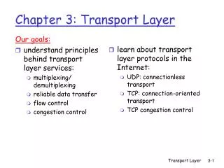
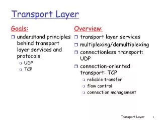
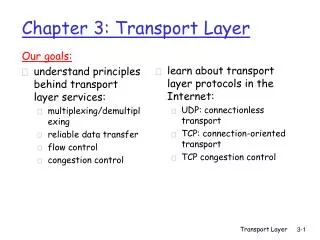
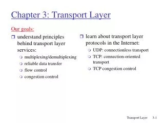
Our goals: understand principles behind transport layer services: multiplexing/demultiplexing reliable data transfer flow control congestion control learn about transport layer protocols in the Internet: UDP: connectionless transport TCP: connection-oriented transport TCP congestion control Chapter 3: Transport Layer Transport Layer
3.1 Transport-layer services 3.2 Multiplexing and demultiplexing 3.3 Connectionless transport: UDP 3.4 Principles of reliable data transfer - LEAVE OUT 3.5 Connection-oriented transport: TCP segment structure reliable data transfer flow control connection management 3.6 Principles of congestion control 3.7 TCP congestion control Chapter 3 outline Transport Layer
provide logical communication between app processes running on different hosts transport protocols run in end systems send side: breaks app messages into segments, passes to network layer rcv side: reassembles segments into messages, passes to app layer more than one transport protocol available to apps Internet: TCP and UDP application transport network data link physical application transport network data link physical network data link physical network data link physical network data link physical network data link physical network data link physical logical end-end transport Transport services and protocols Transport Layer
network layer: logical communication between hosts transport layer: logical communication between processes relies on, enhances, network layer services Household analogy: 12 kids sending letters to 12 kids processes = kids app messages = letters in envelopes hosts = houses transport protocol = Ann and Bill network-layer protocol = postal service Transport vs. network layer Transport Layer
reliable, in-order delivery (TCP) congestion control flow control connection setup unreliable, unordered delivery: UDP no-frills extension of “best-effort” IP services not available: delay guarantees bandwidth guarantees application transport network data link physical application transport network data link physical network data link physical network data link physical network data link physical network data link physical network data link physical logical end-end transport Internet transport-layer protocols Transport Layer
3.1 Transport-layer services 3.2 Multiplexing and demultiplexing 3.3 Connectionless transport: UDP 3.4 Principles of reliable data transfer 3.5 Connection-oriented transport: TCP segment structure reliable data transfer flow control connection management 3.6 Principles of congestion control 3.7 TCP congestion control Chapter 3 outline Transport Layer
application application application transport transport transport P4 P2 P3 P1 P1 network network network link link link physical physical physical Multiplexing at send host: Demultiplexing at rcv host: host 3 host 2 host 1 Multiplexing/demultiplexing delivering received segments to correct socket gathering data from multiple sockets, enveloping data with header (later used for demultiplexing) = socket = process Transport Layer
host receives IP datagrams each datagram has source IP address, destination IP address each datagram carries 1 transport-layer segment each segment has source, destination port number (recall: well-known port numbers for specific applications) host uses IP addresses & port numbers to direct segment to appropriate socket How demultiplexing works 32 bits source port # dest port # other header fields application data (message) TCP/UDP segment format Transport Layer
Create sockets with port numbers: DatagramSocket mySocket1 = new DatagramSocket(99111); DatagramSocket mySocket2 = new DatagramSocket(99222); UDP socket identified by two-tuple: (dest IP address, dest port number) When host receives UDP segment: checks destination port number in segment directs UDP segment to socket with that port number IP datagrams with different source IP addresses and/or source port numbers directed to same socket Connectionless demultiplexing Transport Layer
P3 P2 P1 P1 SP: 9157 client IP: A DP: 6428 Client IP:B server IP: C SP: 5775 SP: 6428 SP: 6428 DP: 6428 DP: 9157 DP: 5775 Connectionless demux (cont) DatagramSocket serverSocket = new DatagramSocket(6428); SP provides “return address” Transport Layer
TCP socket identified by 4-tuple: source IP address source port number dest IP address dest port number recv host uses all four values to direct segment to appropriate socket Server host may support many simultaneous TCP sockets: each socket identified by its own 4-tuple Web servers have different sockets for each connecting client non-persistent HTTP will have different socket for each request Connection-oriented demux Transport Layer
SP: 9157 SP: 5775 P1 P1 P2 P4 P3 P6 P5 client IP: A DP: 80 DP: 80 Connection-oriented demux (cont) S-IP: B D-IP:C SP: 9157 DP: 80 Client IP:B server IP: C S-IP: A S-IP: B D-IP:C D-IP:C Transport Layer
SP: 9157 SP: 5775 P1 P1 P2 P3 client IP: A DP: 80 DP: 80 Connection-oriented demux: Threaded Web Server P4 S-IP: B D-IP:C SP: 9157 DP: 80 Client IP:B server IP: C S-IP: A S-IP: B D-IP:C D-IP:C Transport Layer
3.1 Transport-layer services 3.2 Multiplexing and demultiplexing 3.3 Connectionless transport: UDP 3.4 Principles of reliable data transfer 3.5 Connection-oriented transport: TCP segment structure reliable data transfer flow control connection management 3.6 Principles of congestion control 3.7 TCP congestion control Chapter 3 outline Transport Layer
“no frills,” “bare bones” Internet transport protocol “best effort” service, UDP segments may be: lost delivered out of order to app connectionless: no handshaking between UDP sender, receiver each UDP segment handled independently of others Why is there a UDP? no connection establishment (which can add delay) simple: no connection state at sender, receiver small segment header no congestion control: UDP can blast away as fast as desired UDP: User Datagram Protocol [RFC 768] Transport Layer
often used for streaming multimedia apps loss tolerant rate sensitive other UDP uses DNS SNMP reliable transfer over UDP: add reliability at application layer application-specific error recovery! UDP: more 32 bits source port # dest port # Length, in bytes of UDP segment, including header checksum length Application data (message) UDP segment format Transport Layer
Sender: treat segment contents as sequence of 16-bit integers checksum: addition (1’s complement sum) of segment contents sender puts checksum value into UDP checksum field Receiver: compute checksum of received segment check if computed checksum equals checksum field value: NO - error detected YES - no error detected. But maybe errors nonetheless? More later …. UDP checksum Goal: detect “errors” (e.g., flipped bits) in transmitted segment Transport Layer
Internet Checksum Example • Note • When adding numbers, a carryout from the most significant bit needs to be added to the result • Example: add two 16-bit integers 1 1 1 1 0 0 1 1 0 0 1 1 0 0 1 1 0 1 1 1 0 1 0 1 0 1 0 1 0 1 0 1 0 1 1 1 0 1 1 1 0 1 1 1 0 1 1 1 0 1 1 1 1 0 1 1 1 0 1 1 1 0 1 1 1 1 0 0 1 0 1 0 0 0 1 0 0 0 1 0 0 0 0 1 1 wraparound sum checksum Transport Layer
3.1 Transport-layer services 3.2 Multiplexing and demultiplexing 3.3 Connectionless transport: UDP 3.4 Principles of reliable data transfer 3.5 Connection-oriented transport: TCP segment structure reliable data transfer flow control connection management 3.6 Principles of congestion control 3.7 TCP congestion control Chapter 3 outline Transport Layer
full duplex data: bi-directional data flow in same connection MSS: maximum segment size connection-oriented: handshaking (exchange of control msgs) init’s sender, receiver state before data exchange flow controlled: sender will not overwhelm receiver point-to-point: one sender, one receiver reliable, in-order byte steam: no “message boundaries” pipelined: TCP congestion and flow control set window size send & receive buffers TCP: OverviewRFCs: 793, 1122, 1323, 2018, 2581 Transport Layer
32 bits source port # dest port # sequence number acknowledgement number head len not used Receive window U A P R S F checksum Urg data pnter Options (variable length) application data (variable length) TCP segment structure URG: urgent data (generally not used) counting by bytes of data (not segments!) ACK: ACK # valid PSH: push data now (generally not used) # bytes rcvr willing to accept RST, SYN, FIN: connection estab (setup, teardown commands) Internet checksum (as in UDP) Transport Layer
Seq. #’s: byte stream “number” of first byte in segment’s data ACKs: seq # of next byte expected from other side cumulative ACK Q: how receiver handles out-of-order segments A: TCP spec doesn’t say, - up to implementor time TCP seq. #’s and ACKs Host B Host A User types ‘C’ Seq=42, ACK=79, data = ‘C’ host ACKs receipt of ‘C’, echoes back ‘C’ Seq=79, ACK=43, data = ‘C’ host ACKs receipt of echoed ‘C’ Seq=43, ACK=80 simple telnet scenario Transport Layer
Q: how to set TCP timeout value? longer than RTT but RTT varies too short: premature timeout unnecessary retransmissions too long: slow reaction to segment loss Q: how to estimate RTT? SampleRTT: measured time from segment transmission until ACK receipt ignore retransmissions SampleRTT will vary, want estimated RTT “smoother” average several recent measurements, not just current SampleRTT TCP Round Trip Time and Timeout Transport Layer
TCP Round Trip Time and Timeout EstimatedRTT = (1- )*EstimatedRTT + *SampleRTT • Exponential weighted moving average • influence of past sample decreases exponentially fast • typical value: = 0.125 Transport Layer
Example RTT estimation: Transport Layer
Setting the timeout EstimtedRTT plus “safety margin” large variation in EstimatedRTT -> larger safety margin first estimate of how much SampleRTT deviates from EstimatedRTT: TCP Round Trip Time and Timeout DevRTT = (1-)*DevRTT + *|SampleRTT-EstimatedRTT| (typically, = 0.25) Then set timeout interval: TimeoutInterval = EstimatedRTT + 4*DevRTT Transport Layer
3.1 Transport-layer services 3.2 Multiplexing and demultiplexing 3.3 Connectionless transport: UDP 3.4 Principles of reliable data transfer 3.5 Connection-oriented transport: TCP segment structure reliable data transfer flow control connection management 3.6 Principles of congestion control 3.7 TCP congestion control Chapter 3 outline Transport Layer
TCP creates rdt service on top of IP’s unreliable service Pipelined segments Cumulative acks TCP uses single retransmission timer Retransmissions are triggered by: timeout events duplicate acks Initially consider simplified TCP sender: ignore duplicate acks ignore flow control, congestion control TCP reliable data transfer Transport Layer
data rcvd from app: Create segment with seq # seq # is byte-stream number of first data byte in segment start timer if not already running (think of timer as for oldest unacked segment) expiration interval: TimeOutInterval timeout: retransmit segment that caused timeout restart timer Ack rcvd: If acknowledges previously unacked segments update what is known to be acked start timer if there are outstanding segments TCP sender events: Transport Layer
NextSeqNum = InitialSeqNum SendBase = InitialSeqNum loop (forever) { switch(event) event: data received from application above create TCP segment with sequence number NextSeqNum if (timer currently not running) start timer pass segment to IP NextSeqNum = NextSeqNum + length(data) event: timer timeout retransmit not-yet-acknowledged segment with smallest sequence number start timer event: ACK received, with ACK field value of y if (y > SendBase) { SendBase = y if (there are currently not-yet-acknowledged segments) start timer } } /* end of loop forever */ TCP sender(simplified) • Comment: • SendBase-1: last • cumulatively ack’ed byte • Example: • SendBase-1 = 71;y= 73, so the rcvrwants 73+ ;y > SendBase, sothat new data is acked Transport Layer
Host A Host B Seq=92, 8 bytes data ACK=100 Seq=92 timeout timeout X loss Seq=92, 8 bytes data ACK=100 time time lost ACK scenario TCP: retransmission scenarios Host A Host B Seq=92, 8 bytes data Seq=100, 20 bytes data ACK=100 ACK=120 Seq=92, 8 bytes data Sendbase = 100 SendBase = 120 ACK=120 Seq=92 timeout SendBase = 100 SendBase = 120 premature timeout Transport Layer
Host A Host B Seq=92, 8 bytes data ACK=100 Seq=100, 20 bytes data timeout X loss ACK=120 time Cumulative ACK scenario TCP retransmission scenarios (more) SendBase = 120 Transport Layer
TCP ACK generation[RFC 1122, RFC 2581] TCP Receiver action Delayed ACK. Wait up to 500ms for next segment. If no next segment, send ACK Immediately send single cumulative ACK, ACKing both in-order segments Immediately send duplicate ACK, indicating seq. # of next expected byte Immediate send ACK, provided that segment startsat lower end of gap Event at Receiver Arrival of in-order segment with expected seq #. All data up to expected seq # already ACKed Arrival of in-order segment with expected seq #. One other segment has ACK pending Arrival of out-of-order segment higher-than-expect seq. # . Gap detected Arrival of segment that partially or completely fills gap Transport Layer
Time-out period often relatively long: long delay before resending lost packet Detect lost segments via duplicate ACKs. Sender often sends many segments back-to-back If segment is lost, there will likely be many duplicate ACKs. If sender receives 3 ACKs for the same data, it supposes that segment after ACKed data was lost: fast retransmit:resend segment before timer expires Fast Retransmit Transport Layer
Fast retransmit algorithm: event: ACK received, with ACK field value of y if (y > SendBase) { SendBase = y if (there are currently not-yet-acknowledged segments) start timer } else { increment count of dup ACKs received for y if (count of dup ACKs received for y = 3) { resend segment with sequence number y } a duplicate ACK for already ACKed segment fast retransmit Transport Layer
3.1 Transport-layer services 3.2 Multiplexing and demultiplexing 3.3 Connectionless transport: UDP 3.4 Principles of reliable data transfer 3.5 Connection-oriented transport: TCP segment structure reliable data transfer flow control connection management 3.6 Principles of congestion control 3.7 TCP congestion control Chapter 3 outline Transport Layer
receive side of TCP connection has a receive buffer: speed-matching service: matching the send rate to the receiving app’s drain rate flow control sender won’t overflow receiver’s buffer by transmitting too much, too fast TCP Flow Control • app process may be slow at reading from buffer Transport Layer
(Suppose TCP receiver discards out-of-order segments) spare room in buffer = RcvWindow = RcvBuffer-[LastByteRcvd - LastByteRead] Rcvr advertises spare room by including value of RcvWindow in segments Sender limits unACKed data to RcvWindow guarantees receive buffer doesn’t overflow TCP Flow control: how it works Transport Layer
3.1 Transport-layer services 3.2 Multiplexing and demultiplexing 3.3 Connectionless transport: UDP 3.4 Principles of reliable data transfer 3.5 Connection-oriented transport: TCP segment structure reliable data transfer flow control connection management 3.6 Principles of congestion control 3.7 TCP congestion control Chapter 3 outline Transport Layer
Recall:TCP sender, receiver establish “connection” before exchanging data segments initialize TCP variables: seq. #s buffers, flow control info (e.g. RcvWindow) client: connection initiator Socket clientSocket = new Socket("hostname","port number"); server: contacted by client Socket connectionSocket = welcomeSocket.accept(); Three way handshake: Step 1:client host sends TCP SYN segment to server specifies initial seq # no data Step 2:server host receives SYN, replies with SYNACK segment server allocates buffers specifies server initial seq. # Step 3: client receives SYNACK, replies with ACK segment, which may contain data TCP Connection Management Transport Layer
Closing a connection: client closes socket:clientSocket.close(); Step 1:client end system sends TCP FIN control segment to server Step 2:server receives FIN, replies with ACK. Closes connection, sends FIN. client server close FIN ACK close FIN ACK timed wait closed TCP Connection Management (cont.) Transport Layer
Step 3:client receives FIN, replies with ACK. Enters “timed wait” - will respond with ACK to received FINs Step 4:server, receives ACK. Connection closed. Note:with small modification, can handle simultaneous FINs. TCP Connection Management (cont.) client server closing FIN ACK closing FIN ACK timed wait closed closed Transport Layer
TCP Connection Management (cont) TCP server lifecycle TCP client lifecycle Transport Layer