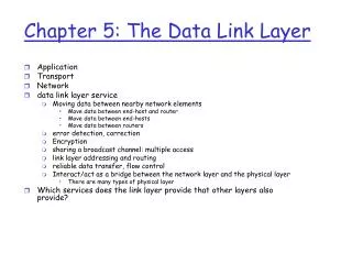
Chapter 5: The Data Link Layer
Application Transport Network data link layer service Moving data between nearby network elements Move data between end-host and router Move data between end-hosts Move data between routers error detection, correction Encryption sharing a broadcast channel: multiple access

Chapter 5: The Data Link Layer
E N D
Presentation Transcript
Application Transport Network data link layer service Moving data between nearby network elements Move data between end-host and router Move data between end-hosts Move data between routers error detection, correction Encryption sharing a broadcast channel: multiple access link layer addressing and routing reliable data transfer, flow control Interact/act as a bridge between the network layer and the physical layer There are many types of physical layer Which services does the link layer provide that other layers also provide? Chapter 5: The Data Link Layer
5.1 Introduction and services 5.2 Error detection and correction 5.3Multiple access protocols 5.4 Link-layer Addressing and routing (ARP) 5.5 Ethernet 5.6 Link-layer switches 5.7 PPP 5.8 Link virtualization: ATM, MPLS Link Layer
Some terminology: hosts and routers are nodes communication channels that connect adjacent nodes along communication path are links wired links wireless links LANs layer-2 packet is a frame,encapsulates datagram data-link layer has responsibility of transferring datagram from one node to adjacent node over one or more links - Without visiting any layer 3 nodes Link Layer: Introduction
datagram transferred by different link protocols over different links: e.g., Ethernet on first link, frame relay on intermediate links, 802.11 on last link each link protocol provides different services e.g., may provide reliability over link transportation analogy trip from Newark to San Jose limo: Newark to PHL plane: PHL to SFO BART: SFO to SF train: SF to San Jose tourist = datagram transport segment = communication link transportation mode = link layer protocol Note that a bus or plane trip might contain many changes of the bus or plane, but this seems like a single hop travel agent = routing algorithm Link layer: context
Link Layer Services • framing, link access: • encapsulate datagram into frame, adding header, trailer • channel access if shared medium • “MAC” addresses used in frame headers to identify source, dest • different from IP address! • Routing • reliable delivery between adjacent nodes • we learned how to do this already (chapter 3)! • seldom used on low bit-error link (fiber, some twisted pair) • wireless links: high error rates • Q: why both link-level and end-end reliability?
Link Layer Services (more) • flow control: • pacing between adjacent sending and receiving nodes • Encryption • Some links can easily be tapped, so encryption is needed for privacy • error detection: • errors caused by signal attenuation, noise. • receiver detects presence of errors: • signals sender for retransmission or drops frame • error correction: • receiver identifies and corrects bit error(s) without resorting to retransmission • half-duplex and full-duplex • with half duplex, nodes at both ends of link can transmit, but not at same time
in each and every host in the network Which other layers are implemented in every host? link layer implemented in “adaptor” (aka network interface card NIC) Ethernet card, PCMCI card, 802.11 card implements link, physical layer attaches into host’s system buses combination of hardware, software, firmware application transport network link link physical Where is the link layer implemented? host schematic cpu memory host bus (e.g., PCI) controller physical transmission network adapter card
sending side: encapsulates datagram in frame adds error checking bits, rdt, flow control, etc. receiving side looks for errors, rdt, flow control, etc extracts datagram passes to upper layer at receiving side Moves frame to another link Adaptors Communicating datagram datagram controller controller receiving host sending host datagram frame
5.1 Introduction and services 5.2 Error detection and correction 5.3Multiple access protocols 5.4 Link-layer Addressing 5.5 Ethernet 5.6 Link-layer switches 5.7 PPP 5.8 Link Virtualization: ATM. MPLS Link Layer
Error Detection • EDC= Error Detection and Correction bits (redundancy) • D = Data protected by error checking, may include header fields • Error detection not 100% reliable! • protocol may miss some errors, but rarely • larger EDC field yields better detection and correction otherwise
Parity Checking Two Dimensional Bit Parity: Detect and correct single bit errors Single Bit Parity: Detect single bit errors 0 0
Sender: treat segment contents as sequence of 16-bit integers checksum: addition (1’s complement sum) of segment contents sender puts checksum value into UDP checksum field Receiver: compute checksum of received segment check if computed checksum equals checksum field value: NO - error detected YES - no error detected. But maybe errors nonetheless? Internet checksum (review) Goal: detect “errors” (e.g., flipped bits) in transmitted packet (note: used at transport layer only)
Checksumming: Cyclic Redundancy Check • view data bits, D, as a binary number • choose r+1 bit pattern (generator), G • goal: choose r CRC bits, R, such that • <D,R> exactly divisible by G (modulo 2) • receiver knows G, divides <D,R> by G. If non-zero remainder: error detected! • can detect all burst errors less than r+1 bits • widely used in practice (Ethernet, 802.11 WiFi, ATM)
CRC Example Want: D.2r XOR R = nG equivalently: D.2r = nG XOR R equivalently: if we divide D.2r by G, want remainder R D.2r G R = remainder[ ]
5.1 Introduction and services 5.2 Error detection and correction 5.3Multiple access protocols 5.4 Link-layer Addressing 5.5 Ethernet 5.6 Link-layer switches 5.7 PPP 5.8 Link Virtualization: ATM, MPLS Link Layer
Multiple Access Links and Protocols Two types of “links”: • point-to-point • PPP for dial-up access • point-to-point link between Ethernet switch and host • broadcast (shared wire or medium) • old-fashioned Ethernet • 802.11 wireless LAN humans at a cocktail party (shared air, acoustical) shared wire (e.g., cabled Ethernet) shared RF (e.g., 802.11 WiFi) shared RF (satellite)
Multiple Access Control (MAC) protocols • single shared broadcast channel • two or more simultaneous transmissions by nodes: interference • collision if node receives two or more signals at the same time multiple access protocol • An algorithm that determines how nodes share channel, i.e., determine when node can transmit • communication about channel sharing must use channel itself! • out-of-band channel for coordination is difficult
Ideal Multiple Access Protocol Broadcast channel of rate R bps 1. when one node wants to transmit, it can send at rate R. 2. when M nodes want to transmit, each can send at average rate R/M 3. fully decentralized: • no special node to coordinate transmissions • no synchronization of clocks, slots • Generally, centralized MAC are much more efficient 4. simple
MAC Protocols: a taxonomy Three broad classes: • Channel Partitioning • divide channel into smaller “pieces” (time slots, frequency, code) • allocate piece to node for exclusive use • this approach is difficult since we know that statistical multiplexing can support more users • Random Access • channel not divided, allow collisions • Detect and recover from collisions • Detection and recovery (e.g., retransmission) can be inefficient • Predictable/guaranteed performance is difficult to achieve • Centralized/taking turns
Channel Partitioning MAC protocols: TDMA TDMA: time division multiple access • access to channel in "rounds" • each station gets fixed length slot (length = pkt trans time) in each round • unused slots go idle • GSM (some cell phones) uses TDMA • Why? • So service is predictable and calls can be rejected if there is not enough bandwidth • example: 6-station LAN, 1,3,4 have pkt, slots 2,5,6 idle 6-slot frame 3 3 4 4 1 1
Channel Partitioning MAC protocols: FDMA FDMA: frequency division multiple access • channel spectrum divided into frequency bands • each station assigned fixed frequency band • unused transmission time in frequency bands go idle • GSM also uses FDMA • example: 6-station LAN, 1,3,4 have pkt, frequency bands 2,5,6 idle time frequency bands FDM cable
Random Access Protocols • When node has packet to send • transmit at full channel data rate R. • no a priori coordination among nodes • Some approaches use limited coordination • two or more transmitting nodes ➜ “collision”, • random access MAC protocol specifies: • how to detect collisions • how to recover from collisions (e.g., via delayed retransmissions) • Examples of random access MAC protocols: • slotted ALOHA • ALOHA • CSMA, CSMA/CD, CSMA/CA
The ALOHA Protocol • Developed @ U of Hawaii in early 70’s. • Packet radio networks. • “Free for all”: whenever station has a frame to send, it does so. • Aloha is the simplest of MAC protocols • Aloha is old but still widely used • As will be seen, many protocols have a period of time where nodes transmits when they want. • During such periods of time, the MAC essentially Aloha
Collisions • Invalid frames may be caused by channel noise or • Because other station(s) transmitted at the same time: collision. • Collisions and other link layer losses must be detected and corrected • Question 1. Where are all the places that losses can occur? • Question 2: where can errors be detected and corrected • Roughly speaking, a collision happens even when the last bit of a frame overlaps with the first bit of the next frame.
If another node transmits here, then there is a collision vulnerable If another node starts to transmit during this vulnerable period, then a collision will occur ALOHA’s Performance 1 t0+t t0+3t t0 t0+2t Time
ALOHA’s Performance • Assume that users try to send frames at random times (Poisson events). • Let G be the average rate that users try to send frames per frame time • G is the utilization • The probability of trying to send k frames during the vulnerable period (which is TWO frame times long) is The probability zero other frames are sent is P(0)=e-2G. The throughput is the rate that frames are sent multiplied by the probability that the transmission is successful G e-2G
Poisson process events Events are distributed according to a Poisson process with parameter if P(k events in period of length T) = exp(-T)(T)k / k! is the rate that events occur = number of events in period T/T (when T is large)
Aloha performance P(k events in period of length T) = exp(-T)(T)k / k! vulnerability period The probability of no collision is probability of no event in the vulnerability period = 2T • Let T = 1 (i.e., our time is measured in packet transmission times, not seconds) • Then what is ? • = average number of transmission attempts per transmission time. • So = utilization. I.e., = G. • And the probability of no collision is exp(-2G)(2G)0/0!=exp(-2G)
ALOHA’s Performance The best throughput occurs for what value of G? What is this best throughput?
If a frame is transmitted here, then a collision occurs But this will only happen if a packet arrives at the MAC layer during this period vulnerable If another node selects to transmit during this vulnerable period, then a collision will occur Slotted Aloha – frames are only transmitted during slots, they cannot cross slot boundaries Time t0+t t0+3t t0 t0+2t The vulnerable period is half the size of unslotted aloha
Slotted Aloha • Vulnerable period is halved. • Doubles performance of ALOHA. • Throughput=S = G e-G. • S = Smax = 1/e = 0.368 for G = 1. • G=1 means typically a node tries to transmit each slot • However, the throughput is well below 1; there any many collisions
Pros single active node can continuously transmit at full rate of channel decentralized simple Cons Collisions wasting slots Inefficient idle slots nodes may be able to detect collision in less than time to transmit packet Slotted aloha requires clock synchronization Lose synchronization requires guard times, which reduces efficiency ALOHA and Slotted ALOHA
CSMA (Carrier Sense Multiple Access) CSMA: listen before transmit: If channel sensed idle: transmit entire frame • If channel sensed busy, defer transmission • human analogy: don’t interrupt others!
Question • For 10 Mbps ethernet, the maximum cable length is 2000m • For 100Mbps ethernet, the maximum cable length is 200m • Why is the maximum length for 100Mbps 10 times shorter than 10Mbps?
CSMA collisions spatial layout of nodes collisions can still occur: propagation delay means two nodes may not hear each other’s transmission collision: entire packet transmission time wasted note: role of distance & propagation delay in determining collision probability
Transmitter 2 Propagation delay Collision detected by transmitter 2 CSMA/CD collision detection Transmitter 1 Position on wire Receiver 1 Receiver 1 receives garbled signal Transmission time time Collision detected by transmitter 1. When is it detected?
CSMA/CD collision detection Transmitter 2 Transmitter 1 Position on wire Receiver 1 Propagation delay Transmission time Receiver 1 receives garbled signal time Collision NOT detected by transmitter 1 Collision detected by transmitter 2 What are the requirements to ensure that collisions are detected? The transmitter must transmit for 2×Tpropagation + epsilon The transmit time is frame length / bit rate Therefore 2×CableLength/speed of propagation + epsilon < FrameLength/bit-rate
CSMA/CD What are the requirements to ensure that collisions are detected? The transmitter must transmit for 2*Tpropagation + epsilon The transmit time is frame length / bit rate Therefore 2×CableLength/speed of propagation + epsilon < FrameLength/bit-rate If frame length can be arbitrarily small, then the cable length must be very short Thus, frames cannot be arbitrarily small. Minimum frame length in Ethernet is 64B. The minimum frame length in Ethernet is independent of bit-rate. Why is the maximum cable length of a 10Mbps ethernet cable 10 times longer than the maximum cable length of a 100Mbps ethernet?
CSMA/CD (Collision Detection) CSMA/CD: carrier sensing with collision detection • collisions detected within short time • colliding transmissions aborted, reducing channel wastage • collision detection: • easy in wired LANs: measure signal strengths, compare transmitted, received signals • Difficult/impossible in wireless LANs: received signal strength overwhelmed by local transmission strength • human analogy: the polite conversationalist
persistent What to do when the link is found to be busy? • 1-persistent • If medium is idle, then transmit. • If medium is not idle, then wait until it is and then transmit. • In this case, all nodes that desire to transmit during the period when a node is transmitting will collide! • p-persistent • If medium is idle, then transmit. • If medium is not idle, then wait until it is idle • Once idle then transmit with probability p. And wait for the next slot with probability 1-p and repeat. • Here slot does not have to be the time to send a full frame, but just enough time to let other hosts start sending. • Exponential Backoff • Next slide
Exponential Backoff • Upon desiring to transmit a frame, set BackOff = BO (some starting value, 4 and 8 are common) • If medium is idle, then transmit. • If medium is not idle, then wait until it is idle • Once idle, • pick an integer, r, between 0 and BO-1 • Wait r time slots • A time slot is long enough so that if a node begins to trasnmit at the beginning of the time slot, then all nodes will hear the transmission before the time slot end • Give an equation for the length of a time slot • If no other transmission begins before the r time slots, then transmit • If a collision is detected, • Continue to transmit so that all nodes will know that a collision occurred, then stop • Set BO = min( 2 * BO , BO_Max ) • In ethernet BO_max = 1024 • Go to step 4 Question: discuss the different ways in which backoff is used in network protocols
“Taking Turns” MAC protocols channel partitioning MAC protocols: • share channel efficiently and fairly at high load • inefficient at low load: delay in channel access, 1/N bandwidth allocated even if only 1 active node! Random access MAC protocols • efficient at low load: single node can fully utilize channel • high load: collision overhead • Be careful. Here we say that high load is when the number of users increases. If the number of users is fixed (and small), then the efficiency under high load is not as bad • “taking turns” protocols • look for best of both worlds! • Use in mobile phones data access • 802.16 aka WiMax partly uses this approach • 802.11 specifies this capability, but it is not widely deployed YET
data data data data poll poll poll poll “Taking Turns” MAC protocols Polling: • master node “invites” slave nodes to transmit in turn master slaves
data data data poll poll poll poll “Taking Turns” MAC protocols Polling: • master node “invites” slave nodes to transmit in turn • After each node is given a chance, the pattern repeats • If a slave has no data to send, then it does nothing, and the master quickly polls the next node master slaves
“Taking Turns” MAC protocols Polling: • master node “invites” slave nodes to transmit in turn • After each node is given a chance, the pattern repeats • If a slave has no data to send, then it does nothing, and the master quickly polls the next node • concerns: • polling overhead • latency • single point of failure (master) master slaves
“Taking Turns” MAC protocols Polling: • master node “invites” slave nodes to transmit in turn • After each node is given a chance, the pattern repeats • If a slave has no data to send, then it does nothing, and the master quickly polls the next node • concerns: • polling overhead • latency • single point of failure (master) • QoS guarantees can be made • If a VoIP call requires 12bps. The master can determine if the call will receive the desire quality and ensure that it does. • When congested, new calls are rejected, but existing call continue to receive good performance • Consider the difference between the demands by VoIP and services provided by TCP • Guarantees are worth much more money than non-guarantees master slaves
“Taking Turns” MAC protocols Token passing: • control token passed from one node to next sequentially. • token message • concerns: • token overhead • Latency • single point of failure (token) T (nothing to send) T data
Summary of MAC protocols • channel partitioning, by time, frequency or code • Time Division, Frequency Division • random access (dynamic), • ALOHA, S-ALOHA, CSMA, CSMA/CD • carrier sensing: easy in some technologies (wire), hard in others (wireless) • CSMA/CD used in Ethernet • CSMA/CA used in 802.11 (We’ll study it when we talk about wireless) • taking turns • polling from central site, token passing • Bluetooth, FDDI, IBM Token Ring
5.1 Introduction and services 5.2 Error detection and correction 5.3Multiple access protocols 5.4 Link-Layer Addressing 5.5 Ethernet 5.6 Link-layer switches 5.7 PPP 5.8 Link Virtualization: ATM, MPLS Link Layer