Balance Tower (P12005)
Balance Tower (P12005) . Vinay Barde : Program Manager Alexis Reusch: Program Facilitator Jason Marks: Lead EE Alfred Lee: Lead CE. Project Overview. Seated balance to help physical therapist teach wheel chair bound patients to improve the strength of their core muscles.


Balance Tower (P12005)
E N D
Presentation Transcript
Balance Tower(P12005) Vinay Barde : Program Manager Alexis Reusch: Program Facilitator Jason Marks: Lead EE Alfred Lee: Lead CE
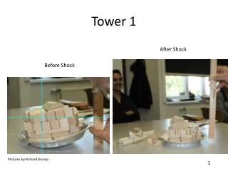
Project Overview • Seated balance to help physical therapist teach wheel chair bound patients to improve the strength of their core muscles. • Currently have a tower that is built that has seven large panels in a vertical line that are separated by 3 tri-colored LEDs. • When activated the LED’s will be blue, if the patient touches the target they will turn green and if they miss they will become red. • There are two games in the MCU : Random & Timed Trial • Second tower will be added to the game to add more challenges for the patients. This tower will be a slave to the first tower and help to increase a patients side to side reaching distance.
Scope & Deliverables • Scope: • Design and build the electrical components of two towers so that they may communicate wirelessly to one another • Perfect software that was developed by team P10005 for the towers to add in a second tower as well as more games and components • Add a measuring device to the outside of the tower so the therapist can measure the distance between the tower and the patient Deliverables: Two functional towers Upgrade current wiring in Tower #1 Populate Tower #2 Wireless Communication between towers Distance Sensor on each tower
Wireless Communication between Towers (Ez430-RF2500 ) Tower #2(Slave) Tower #1(Master) RF Communication ( Transmit/Receive) User Input • Ex430-RF2500 • Frequency @ 2.4 GHZ • Communicates with Evaluation boards through I2C via SimpliciTi protocol
Ez430-RF2500 • 16-MIPS performance • 200-ksps 10-bit SAR ADC • Two built-in operational amplifiers • Watchdog timer, 16-bit Timer_A3 and Timer_B3 • USCI module supporting UART/LIN, (2) SPI, I2C, or IrDA • Five low-power modes drawing as little as 700 nA in standby • 2.4-GHz radio-frequency (RF) transceiver • Programmable data rate up to 500 kbps • Low current consumption • USB debugging and programming interface featuring a driverless installation and application backchannel • 18 available development pins • Highly integrated, ultra-low-power MSP430 MCU with 16-MHz • performance
Test Plan • Test 1: Subsystem/ Function/ Feature Name: Tower Setup • Date Completed: _________________ • Performed By: __________________ • Description: Test the time it will take to set up and perform maintenance on tower(s) for next use.
Test Plan • Test 2: • Subsystem/ Function/ Feature Name: PCB • Date Completed: _________________ • Performed By: __________________ • Description: Perform tests on PCB to verify correct operating conditions.
Test Plan • Test 3: • Subsystem/ Function/ Feature Name: Hardware Test of MCU Connections • Date Completed: _________________ • Performed By: __________________ • Description: Checking input/output lines from MCU for correctness.
Test Plan • Test 4:Subsystem/ Function/ Feature Name: Software • Date Completed: _________________ • Performed By: __________________ • Description: Testing functionality of program, and interaction between peripherals and MCU.
Test Plan • Test 5: • Subsystem/ Function/ Feature Name: Ping Sensor Setup • Date Completed: _________________ • Performed By: __________________ • Description: Test the functional reach test of the sensor for accuracy and distance. Use a piece of black plastic with a bulls eye to test the reach of the laser. Observe the sensor can detect the patient’s hand. Test should be completed 10 times.
Test Plan • Test 6:Subsystem/ Function/ Feature Name: Games • Date Completed: _________________ • Performed By: __________________ • Description: User will play the game and test it for game response, activation time, and if correct operation
Test Plan • Test 7: • Subsystem/ Function/ Feature Name: Functionality of the Capacitive Chip • Date Completed: _________________ • Performed By: __________________ • Description: We will test to see what power we need for all outputs to work reliably. Power and Clock will be applied to the chip. The voltage will and we will vary the sinusoidal signal to make sure all eight outputs are functional.