Download
1 / 87
920 likes | 1.26k Vues
Siemens Safety Systems. NTNU 14.03.2011, Arnt Olav Sveen. Historikk og bakgrunn. Applikasjoner. Krav i IEC61508. Løsninger . Basis for løsninger. Kontroller / sentralsystem. Inngangs og utgangs moduler. Human - Machine Interface. Programvare /programmering. Kommunikasjon / nettverk.

E N D
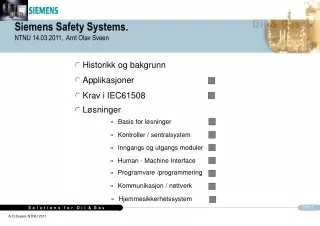
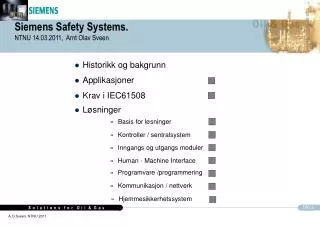
Siemens Safety Systems.NTNU 14.03.2011, Arnt Olav Sveen • Historikk og bakgrunn • Applikasjoner • Krav i IEC61508 • Løsninger • Basis for løsninger • Kontroller / sentralsystem • Inngangs og utgangs moduler • Human - Machine Interface • Programvare /programmering • Kommunikasjon / nettverk • Hjemmesikkerhetssystem
Siemens Safety Systems. The prevention of accidents should not be considered a question of legislation, but instead our responsibility to fellow beings and economic sense (Werner von Siemens in 1880)
SIMATIC S5-115F (1988) Distributed Safety S7 151F/315F/317F/416F (2002/2003) S7 F Systems S7-400FH / PROFIsafe (1999) Safety Matrix (1999) QUADLOG (1995) SIMATIC S5-95F (1994) SIMATIC S5-110F (1980) History of Siemens Safety Systems
Siemens Safety Systems. • First large safety project 1985, Oseberg Feltsenter • To day nearly 30% of installed safety systems in Norwegian part of the North Sea, and numerous deliveries world wide. • First solutions, Simatic PLC's with additional hardware, 2 PLC's running independently. • To-day a full range of S7 F, TÜV verified systems • Work procedures according to IEC61508, SINTEF verified, and a full scope of function blocks and typicals
Siemens Safety Systems, traditional systems. Siemens Safety Systems applications are based on long experience • Stena Don 2000 • Statfjord A 2000 • Snorre B 2000 • Huldra 2000 • Oseberg South 2000 • Embla 2000 • Oseberg Gas 1999 • Troll C 1999 • Statfjord B 1998 • Visund 1998 • Eldfisk WIP 1999 • Oseberg East 1997 • Petrojarl Foinhaven 1996 • Njord A & B 1995 • Statfjord C 1995 • Vigdis 1995 • Ekofisk 1995 • Eldfisk alpha 1993 • Brage 1992 • Embla 1991 • Snorre TLP 1990 • Oseberg A 1988 • Oseberg B 1987
Siemens Safety Systems, S7, PCS7 • HULDRA (Norway) 2000 • MAERSK XL1 /XL2 (worlds largest jack up’s, built in Korea) 2002 • EKOFISK 2/7A 2002 • Visund 2006-2011 • Halfdan 5 platforms (Denmark/built in Singapore and Holland) 2003-2011 • Al Shaheen (28 platforms in Qatar) 2003- 2010 • White Rose FPSO (Canada/ built in Canada/Korea/Abu Dhabi/USA) 2005 • P50, Albacore LesteFPSO (Brazil) , PRA 12005-2007 • FPSOcean 1 (China) 2007-2009 • Santa Fe (USA, 2 drilling Rigs)2004 • Oseberg Field-centre (Norway) (113 off S7 400/400FH , 35000 I/O) 2005 -2007 • Statfjord A/B/C ESD and F&G 2004-2007 • Sevan SSP300-1, 2 and 3 2005-2008 • Deep Sea Driller 1and 2 2007-2011 • Blackford Dolphin 2006-2008 • Snorre TLP 2006-2011 • Tor 2011 • Yme (upgrade) 2011
Safety Systems ApplicationsHva er et sikkerhetssystem (SIS)? Disaster protection Disaster protection Collectionbasin Passive protection Hvor griper det inn i en ulykkesutvikling, og forhåpentligvis stanser den? Overpressure valve, rupturedisc Active protection Safety shutdown Safety InstrumentedSystem (SIS) Safety system (automatic) Process controlsystem Plantpersonnel intervenes Process alarm Process value Basic automation Normal activity
Safety Systems ApplicationsHva er et sikkerhetssystem (SIS)? Safety Instrumented System (SIS) Basic Process Control System (BPCS) Inputs Outputs Inputs Outputs PT 1A PT 1B I / P FT Reactor Low level
Safety Systems ApplicationsOg hva er “Equipment Under Control”, EUC?
Safety Systems ApplicationsPurpose Risk reduction by safety systems, SIS Hensikten med å innføre et sikkerhetssystem, er å få risikoen ned til et akseptabelt nivå.
Safety Systems ApplicationsWhat is Risk? Who decides what is acceptable risk? • Examples of fatality risk figures • Road accident 100cpm 1.0x10⁻⁴/yr 1 av 100 (ved levetid 100 år) • Car accident 150cpm 1.5x10⁻⁴/yr 1,5 av 100 • Accident at work 10cpm 1.0x10⁻⁵/yr 1 av 1000 • Falling Aircraft 0.02 cpm 2.0x10⁻⁸/yr 2 av 1000 000 • Lightning strike 0.1cpm 1.0x10⁻⁷/yr 1 av 100 000 • Insect/Snake bite 0.1cpm 1.0x10⁻⁷/yr 1 av 100 000 • Smoking 20 per day 5000 cpm 5.0x10⁻³/yr 1 av 2 cpm = chances per million of the population (per year)
Unacceptable Risk Region Likelihood Tolerable Risk Region Consequence Safety Systems Applications Risk reduction by safety systems, SIS Containment Dike Hazard #1 Control System Operator Intervention SIL1 SIL2 Safety Instrumented Function SIL3 Risikoreduksjonen er større ved et høyere SIL
Safety Systems Applications What is Safe state? Can the Safety System bring the area or equipment to a safe state? How? What is required?
Safety Systems Applications Some of the Safety Systems Applications • ESD, Emergency Shutdown • F&G, Fire & Gas Detection, Fire-fighting • Process Shutdown • Fire-pump Logic • Ballast Control • Blow-down • Riser release / Anchor Release • Fire Dampers, Active Smoke Control • HIPPS, High Integrity Pressure Protection System
Safety SystemsTopology for total platform control system including safety
F&G Matrix F&G System Topology (the different modules) Redundant Operator Stations Redundant Safety Servers Redundant Integrated Safety & Process Network Redundant Fail Safe Communications – SIL3 (Profisafe) Addressable Fire Detection Systems High Available & Fail Safe CPU’s Redundant Communications Interface Fail Safe I/O Modules
IEC 61508 • The safety level is applicable for: • The total solution • All the projects lifecycles • The system solution covers EUC, including HMI • HW engineering, construction and testing • By use of standard hardware set-up • With special modules approved by TÜV • Software • Function blocks (basic blocks approved by TÜV) • Protocols and drivers approved by TÜV • Application program (according to procedure) • Maintenance procedures • Operation and Modification Procedures
IEC 61508, Implementation according to proven procedures. • Safety requirements shall be specified, and the requirements shall be traceable through all engineering phases. • Internal procedures for development of software according to IEC61508 • Procedures developed in co-operation with SINTEF Tele and Data. • specification • planning • implementation • verification • validation • modifications. • Internal procedures for hardware design and production according to IEC61508 • Made on the same structure as the SINTEF verified SW procedure.
Basic principles to fulfil IEC61508 • Basically three requirements • Quality assurance (98% of IEC61508) • Requirement to availability of safety function(PFD requirement, Probability of Failure on Demand) • Requirement to safe failure fraction(SFF requirment, Safe Failure Fraction) • Answers to the requirements • Work methology, procedures, qualified workers • Equipment quality, redundancy, second resort, diagnostics • Fail to safe design, diagnostics
Diagnostics, feedback and redundancy Diagnostics / feedback Diagnostics will give possibility to repair dangerius errors before an emergency situation, hence improving PFD and SFF. Increased diagnostics also give room for estension of test interval, hence saving cost. Feedback will give opportunity to use second shotdown possibility in case of first possibility failing, hence increasig PFD and SFF. Redundancy / second shutdown fasility More than one shutown fasility, and all are activated at same time, or second fasilities are used as result of feedback when first is faling, will give improved SFF and PFD.
P3 P2 P1 S1 - - - A1 - 1 1 F1 A2 - 1 1 S2 A1 1 2 2 F2 A2 1 3 3 F1 2 3 3 S3 F2 3 4 3 S4 3 4 4 Risk Determination (one of several methods) How to find Required Safety Integrated Level (SIL) of the Safety System Risk Graph S: Severity of injury/damage 1:small injury, minor environmental damage 2:serious irreversible injury of many people involved or a death temporary serious environmental damage 3:death of many people long-term serious environmental damage 4:catastrophic results, many deaths : F: Frequency and/or exposure time to hazard 1:seldom - quite often 2:frequent - continous A: Avoiding hazard 1:possible 2:not possible P: Probability of Occurrence 1:very low 2:low 3:relatively high
Requirement Class (AK) DIN V 19250 Safety Integrity Level (SIL) IEC 61508 Probability of failure on demand per h (constant operation) (IEC 61508) Probability of failure on demand (on demand operation) (IEC 61508) Control Category EN 954-1 AK 1 --- -- -- B AK 2 and 3 SIL 1 10-5 to 10-6 10-1 to 10-2 1 and 2 AK 4 SIL 2 10-6 to 10-5 10-2 to 10-3 3 AK 5 and 6 SIL 3 10-7 to 10-8 10-3 to 10-4 4 AK 7 and 8 SIL 4 10-8 to 10-9 10-4 to 10-x --- Safety Integrity Levels, direct requirement IEC61508 S7-400F/FH by Siemens
Safe failure fraction Hardware fault tolerance 0 1 2 < 60 % SIL1 SIL2 SIL3 60 % - 90 % SIL2 SIL3 SIL4 90 % - 99 % SIL3 SIL4 SIL4 > 99 % SIL3 SIL4 SIL4 Safe failure fraction Hardware fault tolerance 0 1 2 < 60 % not allowed SIL1 SIL2 60 % - 90 % SIL1 SIL2 SIL3 90 % - 99 % SIL2 SIL3 SIL4 > 99 % SIL3 SIL4 SIL4 Safety IntegrityLevels, direct requirement IEC61508IEC61508 requires higher “fail safe fraction” for “intelligent” components Hardware safety integrity: architectural constraints on type A safety-related subsystems Hardware safety integrity: architectural constraints on type B safety-related subsystems
Safety Integrity Levels, PFD calculation Safety reliability Block diagram:
S7-414-4H *) 2.8MB 600 F-I/Os S7-417-4H *) 30MB 3000 F-I/Os S7-412-3H *) 768kB 100 F-I/Os S7-319F-2DP 1.4MB 1000 F-I/Os S7-317F-2DP 1MB 500 F-I/Os S7-315F-2DP192kB 300 F-I/Os Redundant systems Safety Controller S7 FH Safety Control System, SIMATIC S7 – 300/400 F/FH Certified up to SIL 3
Components S7-400F/FH • High available System S7-417FH as a basis • CPU 417-4H with TÜV certified basis SW/HW (SIL3) • TÜV certified failsafe logic SW blocks (SIL3) • Engineering /Hardware Configuration/Programming • Configuration of the S7-400F-Hardware with Standard HW-Config. • Graphical Engineering (programming) with Standard CFC (Continuous Function Chart) • Coexistence of Standard- and F-Applications (SIL3) in one CPU • Connection to the Process Devices • Failsafe I/O modules (SIL1 - 3) • PROFIsafe (extra safety layer to Profibus) (SIL3) to ensure failsafe communication via Profibus-DP
Basic principle “Protected F-Islands” CPU hardware Any faults in other modules, environmental factors Standard user programs CPU operating system Safety-related user program Failsafe I/O modules Safety-related frame
PC Standard Engineering Software F-Programming Tool F-Application Program Standard-CPU 417-4H Standard I/O’s (ET200M) F-I/O’s (ET200M) RUN-P RUN-P RUN RUN STOP STOP CMRES CMRES ProfiSafe Protocol Standard-ProfibusDP S7 400F F/H system - modularity,
PS CPU DE DA AE AA CP PS CPU DE DA AE AA CP I M I M D E D A A E A A F M PROCESS S7-400HRedundancy Principle Synchronization, information and status exchange
Redundant IM 153-2 Profibus-DP L+ IO with active backplane bus performing the switchover L+ Bus module IM Active backplane bus IM I/O ConfigurationSwitching of master by use of redundant Profibus Target: Reduce common mode faults for the switch-over to a minimum Achieved by: Very simple component does the switchover
Without synchronization Cycle synchronization Time synchronization Command synchron. Part. PLC B Part.-PLC A Part. PLC B Part. PLC A Part. PLC A Part. PLC B Part. PLC A Part. PLC B Redundant S7-400HA Synchronization Procedure is required Synchronization of all commands whose execution would trigger different states in both partial PLCs (Siemens Patent)
Flexible Set-up‘sTogether, the listed principles result in a flexible set-up Fail Safe Fail Safe and High Availability • S7-400F • PROFIBUS-DP • F-E/A Moduls • SIL 3, AK6 • redundant S7-400FH • redundant PROFIBUS-DP • F-E/A Moduls • SIL3, AK6 • redundant S7-400FH • redundant PROFIBUS-DP • redundant F-E/A Moduls • SIL3, AK6
AI DI DO DO Flexible Modular Redundancy ™ • Make any component redundant
AI DI DO Flexible Modular Redundancy ™
AI AI DI DI DO DO Flexible Modular Redundancy ™ • Make any component redundant • Physically separate redundant resources
Dual AI AI AI DI DI DO DO AI DO Simplex Triple Flexible Modular Redundancy ™ • Make any component redundant • Physically separate redundant resources • Mix and match redundancy
Dual AI AI AI DI DI DO DO AI DO Simplex Triple Flexible Modular Redundancy ™ • Make any component redundant • Physically separate redundant resources • Mix and match redundancy • Tolerate multiple faults with no impact on safety • Safety is not dependant on redundancy; all components are SIL3-capable • Redundancy only for availability; No degraded mode
AI DI DO AI DO AI DI DO DO AI AI 1oo2 Valves 2oo3 PT Flexible Set-up‘s • Multiple Fault Tolerant • Fieldbus architecture allows system to tolerate multiple faults without interruption • I/O redundancy independent of CPU redundancy • All components rated for SIL3 • No degraded mode • Safety not dependent on redundancy 2oo3
Alternative setup by othersFail Safe and High Availability due to 2oo3 HW voting Sample from Triconex design
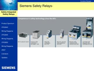
Standard SM´s F-SM´s RUN-P RUN-P RUN RUN STOP STOP CMRES CMRES Input and output modules to SIL 3, 2 and 1 • ET 200 M F-SM, Fail Safe Modules • SIL3, 2 or 1dependant on configuration (TÜV) • SIL 3 also in single configuration for most modules • SIL 3 with single or redundant bus connection • ET200 iSP, zone 1 • Small granularity modules for Zone 1, SIL3 • ET200 S • Small granularity modules can cover SIL1 to SIL3
Architecture S7-300 Fail Safe Modules (sample) F-Digital Output, with built in redundancy, self verification and degrading Bus interface Microcontroller Microcontroller Dual- port RAM Output driver Second disconnection facility If ”Output driver” fails to bring output to safe state, ”0”, the microcontroller does, based on the read back, order the ”Second disconnection facility” to shut the card down Read back Output VSupply L+
S7-300 Fail Safe Modules • Redundant microcontroller in each IO module • Safety Integrated Level • 1oo1 evaluation, SIL 2, AK 4 • 1oo2 evaluation, SIL 3, AK 6, internal in module • Diagnose of internal and external errors • mutual function checking of the microcontrollers • input or output test • branching of the input signals to both microcontrollers • discrepancy analysis of the redundant input signals • readback of the output signals and discrepancy analysis • Second disconnection facility in the case of outputs • Communication with CPU via Profisafe
S7-300 Fail Safe I/O Modules Samples of modules available • SM326F, DI DC24V 24 x SIL2, 12 x SIL3, with diagnostics interrupt • SM326F, DI NAMUR [EEx ib] 8 x SIL2, 4 x SIL3 with diagnostics interrupt • SM326F, DO DC24V/2A 10 x SIL3, current source, diagnostics interrupt • SM336F, AI 4-20mA 6 x SIL2 or 3, with diagnostics interrupt
Fail Safe I/O ModulesLibrary for interfaces to field devices Library with standard, pre-verified instrument interfaces