Download
1 / 49

E N D
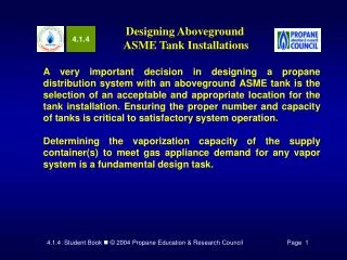
4.1.4 Designing Aboveground ASME Tank Installations A very important decision in designing a propane distribution system with an aboveground ASME tank is the selection of an acceptable and appropriate location for the tank installation.Ensuring the proper number and capacity of tanks is critical to satisfactory system operation. Determining the vaporization capacity of the supply container(s) to meet gas appliance demand for any vapor system is a fundamental design task.
4.1.4 Designing Aboveground ASME Tank Installations • In this module you will learn to: • Identify regulations that govern aboveground ASME tank site selection • Identify steps to finalize an aboveground ASME tank location plan • Identify factors that affect aboveground tanks vaporization capacity • Select propane storage tanks by applying ASME tank vaporization guidelines • Identify other considerations for selecting appropriate ASME tank sizes
4.1.4 Designing Aboveground ASME Tank Installations • In this module you will learn to: • Identify code requirements and components for aboveground ASME manifold tanks in vapor service • Identify components for typical vapor service manifold tank installations with single regulator configuration • Identify code requirements and components for manifold tanks supplying liquid to an auxiliary vaporizer
Aboveground and underground ASME tanks shall be located no closer to important buildings, property lines that can be built upon, ignition sources and building openings than the minimum distances set out in NFPA 58. NFPA 58 NFPA 58 2004 2001 6.3 3.2.2 Regulations that Govern Tank Location Figure 1 presents, in table format, minimum required distances and a brief purpose or explanation of the requirement.
Regulations that Govern Tank Location Figure 1. Minimum Distance Requirements for Stationary ASME Tank Installations
Regulations that Govern Tank Location Figure 1. Minimum Distance Requirements for Stationary ASME Tank Installations
Regulations that Govern Tank Location Figure 1. Minimum Distance Requirements for Stationary ASME Tank Installations
Regulations that Govern Tank Location Figure 2. Aboveground ASME Tank Location Minimum Separation Distances
Regulations that Govern Tank Location The illustrations are presented as a guide or reference only. Always check your company’s SOP and state and local codes. The distance requirements above are based on recommendations in NFPA 58. They do not replace any requirements in your state or local codes. Tanks should always allow space for maintenance. Figure 3. Multi-Tank Installations
Steps to Finalize a Tank Location Plan Some propane marketers have detailed procedures for determining system layout. Always follow local guidelines. Remember, a competent and complete planning effort will produce a satisfied customer.
Sizing ASME Aboveground Tanks for Vapor Service Factors Affecting the Vaporization Rate of Tanks— When a tank(s) is sized for vapor service, make sure the vaporization rate of the tank(s), or withdrawal rate, is equal to or greater than the demand for propane. • Outside Surface Area of the Tank: The heat required to vaporize liquid is transferred through the walls of the tank. If the area of the tank wall which is in contact with the propane liquid (wetted surface area) is large, the total heat (Btu) that can be transferred to the liquid is high. • Level of Liquid Propane in the Tank
Sizing ASME Aboveground Tanks for Vapor Service Figure 4. Effect of Decreased Liquid Level and Wetted Surface Area on Vaporization Rate
Sizing ASME Aboveground Tanks for Vapor Service Factors Affecting the Vaporization Rate of Tanks— • Air Temperature Surrounding the Tank : Because of propane’s relatively low boiling point (-44°F at atmospheric pressure) the heat needed for vaporization is usually available from the air that surrounds the propane storage tank.High summer air temperatures surrounding the tank create more available heat to be transferred to the liquid. As a result, the rate of vaporization is high. However, low outside temperatures in the winter reduce the tank vaporization capacity.
Sizing ASME Aboveground Tanks for Vapor Service Factors Affecting the Vaporization Rate of Tanks— • Location of the Tank. Certain ASME tanks are designed to be installed aboveground or underground. Aboveground tanks have maximum vaporization rates during exposure to high summer temperatures and direct sunlight. However, aboveground tanks may experience a drop in the vaporization rate in the winter due to low temperatures, sustained cloudy skies, and periods of rain, fog, sleet or snowfall.
Sizing ASME Aboveground Tanks for Vapor Service Factors Affecting the Vaporization Rate of Tanks— • Relative Humidity: If the air is moist (high humidity), the air may cool down to a temperature where the moisture will condense on the wetted surface area of the tank & freeze. The resulting "frost line" on the wetted surface acts as an insulator and drastically reduces the vaporization rate of the tank.
Sizing ASME Aboveground Tanks for Vapor Service Figure 5. Estimated Vaporization Rates for Aboveground ASME Tanks
Applying ASME Tank Vaporization Guidelines Seven Sizing Factors— The wide ranges of air temperatures and relative humidity that are experienced in different parts of the United States dictate that the selection of storage tanks be made using the following Seven Sizing Factors: • What is the lowest anticipated temperature for the installation? • What is the highest expected relative humidity? • What is the total gas system demand (Btuh load)? • What does the gas system customer profile tell about anticipated customer demand and critical service factors? • What are the operating characteristics of the connected gas appliances (appliance load factors)? • How does the installation compare to similar gas customers in the immediate area? • What are the propane company guidelines for delivery scheduling?
Applying ASME Tank Vaporization Guidelines Using Tank Vaporization Guides — It is important that persons who select propane tanks for residential and small commercial installations take the time to examine the assumptions and conditions that apply to the tank vaporization guide used. Using a “Rule of Thumb” Guide — (for Small to Medium Propane Demand Systems and Moderate Climate Conditions) The method uses ASME tank dimensions, liquid level, and a constant value for each 10 percent of liquid to estimate the vaporization capacity of a given tank size at 0° F. Additional factors are used to calculate available vapor at other temperatures. The method does not consider relative humidity as a variable, but yields fairly reliable vaporization capacity estimates for moderate demand systems for locations with moderate prevailing weather conditions, such as the southern states and Hawaii.
Applying ASME Tank Vaporization Guidelines “Rule-of-Thumb” Vaporization Capacity for ASME LP-Gas Storage Tanks1 1 Engineered Controls International, Inc. REGO Products LP-Gas Serviceman’s Manual
Applying ASME Tank Vaporization Guidelines “Rule-of-Thumb” Vaporization Capacity for ASME LP-Gas Storage Tanks1 1 Engineered Controls International, Inc. REGO Products LP-Gas Serviceman’s Manual
Applying ASME Tank Vaporization Guidelines Selecting Aboveground ASME Tank(s) for High Demand Systems and Severe Climate Conditions Using a Tank Vaporization Chart— When the seven sizing factors are applied to the gas customer profile illustrated by Figures 7a and 7b, it is apparent that a more detailed method for aboveground tank selection is required for the high-demand system.
Applying ASME Tank Vaporization Guidelines Figure 7a. High-Demand, Severe Service Conditions Customer Profile
Applying ASME Tank Vaporization Guidelines Figure 7a. Example of a Gas Customer Profile (Front)
Applying ASME Tank Vaporization Guidelines Figure 7a. Example of a Gas Customer Profile (Front)
Applying ASME Tank Vaporization Guidelines Figure 7b. High-Demand, Severe Service Conditions Customer Profile
Applying ASME Tank Vaporization Guidelines Figure 7b. Example of a Gas Customer Profile (Back)
Applying ASME Tank Vaporization Guidelines Figure 7b. Example of a Gas Customer Profile (Back)
Applying ASME Tank Vaporization Guidelines Tank Vaporization Chart Method for Selecting Aboveground ASME Tank(s) —
Applying ASME Tank Vaporization Guidelines Figure 8. Determining Effective Load for Use with the Tank Vaporization Chart Note: Calculations at bottom of chart are specific to the Customer Profile in Figure 7.
Applying ASME Tank Vaporization Guidelines Figure 9. Average Appliance Load Factor Chart By Customer Type
Applying ASME Tank Vaporization Guidelines Tank Vaporization Chart Method for Selecting Aboveground ASME Tank(s) —
Applying ASME Tank Vaporization Guidelines Figure 11. Average Highest Relative Humidity for the Month of January
Applying ASME Tank Vaporization Guidelines Tank Vaporization Chart Method for Selecting Aboveground ASME Tank(s) — Figure 12. Vapor Distribution System Operating Factors (Example)
Applying ASME Tank Vaporization Guidelines Figure 13. Estimated Vaporization Rates for Aboveground ASME Tanks NOTE: Refer to Chart Application Criteria for Use
Applying ASME Tank Vaporization Guidelines Tank Vaporization Chart Method for Selecting Aboveground ASME Tank(s) — If the tanks listed in the tables do not provide the vaporization rate to meet the effective load of the appliances, there are four options that might be used: • Manifold two or more tanks together. • Install an underground tank. • Choose a larger capacity tank. • Change to liquid withdrawal and install a vaporizer.
Other Considerations in Tank Selection Frost Lines — The first consideration for proper tank sizing with regard to vaporization capacity is to ensure that the tanks that are installed do not develop a frost line under peak demand and severe operating conditions. If the supply tank(s) consistently develop a frost line when the liquid level is above 20%, the tank is too small for the load, and larger tank(s) should be installed. Efficient and Reliable Delivery Schedule— Figure 14 can be used to estimate the initial frequency of required delivery scheduling for a customer account.
Other Considerations in Tank Selection Figure 14. Example of a Delivery Scheduling Chart
Other Considerations in Tank Selection • Summary of Sizing Considerations — • Proper selection of ASME tanks is one key to customer satisfaction. • Tanks must be sized using the most severe anticipated conditions. • Preparing a gas customer profile provides important information, and knowing how the customer gas appliances will be used are the basis for sizing and selecting propane supply tanks. • Supply tank selection must consider any critical service factors. • If the supply tank(s) are not capable of supplying sufficient volume of vapor at the minimum required supply pressure (10 psig), auxiliary vaporizing equipment should be used. • Service technicians, and especially, delivery personnel should report the formation of frost or ice on customer propane tanks.
NFPA 58 NFPA 58 2004 2001 5.7.7.1(F) 2.3.3.2(a)(4) Code Requirements for Manifold Tank Installations Most propane system installers and jurisdictional authorities interpret 2.3.3.2 (a)(4) as a requirement for excess-flow protection in manifold tank installations where the first-stage regulator is connected to tank service valves using vapor piping longer than the pigtail used in typical single tank installations and where the regulator is installed outside of the tank dome.
Selecting Components for Manifold Tank Installations Figure 16. Excess-Flow POL Fitting Figure 15. Manifold Aboveground ASME Tanks
Selecting Components for Manifold Tank Installations Figure 18. POL Back Check Tee Figure 17. Manifold Underground ASME Tanks
Selecting Components for Manifold Tank Installations • Special components for manifold underground tank installations: • Regulator vent pipe-away assembly • POL back check tees • Open-bottom water meter or valve box, or poured-in-place concrete vault with loose-fitting manhole cover
ASME containers that have liquid interconnections shall be installed so that the maximum permitted filling level of each container is at the same elevation. NFPA 58 NFPA 58 2004 2001 6.6.3.2 3.2.6.2 Requirements for Manifold Tanks in Liquid Service • If the actuated liquid withdrawal excess-flow valve (sometimes called an evacuation valve) is used for manifold tank connection, one of two forms of excess-flow protection must be provided: • A liquid transfer valve attached to an actuated liquid withdrawal excess-flow valve that is recommended by the manufacturer for continuous service; or • The actuated liquid withdrawal excess-flow valve must be removed and replaced with a liquid transfer valve equipped with an internal excess-flow.
Requirements for Manifold Tanks in Liquid Service Bottom Opening Liquid Withdrawal Top Opening Liquid Withdrawal Figure 20. Internal Valve with Excess-Flow and Cutaway View Figure 19. Excess- Flow Angle Valve
Requirements for Manifold Tanks in Liquid Service Liquid piping sections that can be closed at each end must be protected by the installation of a hydrostatic relief valve. Hydrostatic relief valves should have a 400 to 450 psig start to discharge rating. Figure 21. Hydrostatic Relief Valve Typically, liquid piping for manifold tanks is comprised of threaded schedule 80 pipe sections and heavy (2000 or 3000 pound) forged steel fittings.
Figure 22. Stainless Steel Braided Flexible Piping Section Requirements for Manifold Tanks in Liquid Service Figure 23. Slab for Manifold Liquid Service Tanks
Time to See If You Got the Key Points of This Module… • Complete the Review on pages 30 - 33. • See if you are ready for the Certification Exam by checking off the performance criteria on pages 34 - 36.