Comprehensive Guide to CFD Analysis Process
270 likes | 519 Vues
Learn the main steps in Computational Fluid Dynamics (CFD) analysis, from geometry design to post-processing, including geometry creation, meshing, physics definition, solver setup, and post-processing techniques.

Comprehensive Guide to CFD Analysis Process
E N D
Presentation Transcript
CFX-10 Introduction Lecture 1
CFX-10 Introduction • Main Steps in CFD Analysis Geometry Meshing Physics Definition Solver Post-processing
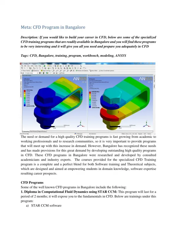
Step 1: Geometry DesignModeler or Import from CAD create a solid representing the fluid flow region Step 2: Meshing CFX-Mesh, CFX-TurboGrid or ICEM create a volume mesh using the solid Step 3: Physics Definition CFX-Pre define physical models, material properties and boundary conditions Step 4: Solver CFX-Solver Manager solve equations and produce a solution Step 5: Post-processing CFX-Post analyze and visualize the solver results Main Steps in CFD Analysis
Step 1: Geometry DesignModeler or CAD
Geometry • Create or Import the geometry • Domain in which the governing equations will be solved and solution obtained • ANSYS DesignModeler can be used to create geometry • Results in one or more bodies • Not required if the mesh is imported from a separate application
Step 2: Meshing CFX-Mesh, ICEM or CFX-TurboGrid
Meshing • Mesh Generation • Process of generating finite volumes or elements • CFX can accept meshes with elements that are hexahedral, tetrahedral, prismatic (wedges), pyramids or any combination • Surface mesh and volume mesh make up the mesh • Meshes can be created in a different session or imported from another meshing utility
Step 3: Physics Definition CFX-Pre
Import Mesh into CFX-Pre • The mesh defines the fluid domain(s) to be solved • Mesh Tab imports and manages grids • Each imported mesh is stored as a Mesh Assembly • Import Mesh • Transform Mesh Assembly • Delete Mesh Assembly • Edit Render Options for Selected Regions • View Mesh Statistics for Selected Regions
Create Toolbar • To define your simulation, follow the toolbar from left to right • Some items are optional, depending on your simulation • Hold the mouse over each icon to see what it does
Create Toolbar • In the simplest cases, the following items are required after importing the mesh 3. Solver Control 1. Domains 4. Write Solve File 2. Boundary Conditions
Create Toolbar Create a Coordinate Frame – if the default coordinate frame is not sufficient Define the Simulation Type – steady state (default) or transient Create a Domain – define properties of fluid, solid and/or porous domain(s) Create a Subdomain – if you need to apply sources within a domain Create a Source Point – if you need to apply a point source within a domain Create a Boundary Condition – define what’s happening at the boundaries Create a Domain Interface – for periodicity and to connect multiple domains Define the Global Initial Conditions – initial conditions for all domains Define the Mesh Adaption Criteria – to adapt the mesh as the solution progresses Define the Solver Control Criteria – the parameters that control the Solver Output Control and Monitor Points – the files the Solver outputs Write Solver File – write a file and proceed to the Solver
Domains • Define the regions in which the equations are solved • Fluid, solid and porous regions • Pick the fluid(s) or solid materials • Select the physical models: • Turbulence and Heat Transfer model • Buoyancy • Multiphase models • Combustion and Radiation models • Particle Tracking ……
Boundary Conditions • Boundary Conditions are needed to completely specify (or close) the problem • Required on all external surfaces of geometry • Boundary values can be constants or CEL expressions • A Default Boundary Condition is applied to external surfaces which have not been explicitly defined • created automatically for each domain • All mesh regions are available in CFX-Post, not just Boundary Conditions
Boundary Conditions • There are 5 general types of boundary conditions • INLET: allow flow into the domain only • OUTLET: allow flow out of the domain only • OPENING: allow flow in and out of the domain • WALL: no flow, normal velocity is zero • SYMMETRY: flat surface specifying plane of symmetry
Solver Control • Control of the CFX-5 Solver is undertaken by the use of Solver Parameters, set on the Solver Control form • Convergence Control • maximum number of iterations • timescale selection • Advection Scheme • Convergence criteria • MAX or RMS residual • conservation target
Write Solver File • CFX-Pre writes out a “Definition” (.def) file to run in the Solver • Contains everything needed (mesh and physics) to run the simulation. • CFX-Pre stores mesh data in the “Geometry, Topology and Mesh” (.gtm) file and physics in the .cfx file • Keep these files to re-open simulations in CFX-Pre
Step 4: Solver CFX-Solver Manager
Solver • Solve the governing equations • Set the flow solver options • Iteratively solve the governing equations as a batch process • Obtain convergence
Solver Manager • The Solver Manager is primarily used to: • start a new calculation, or set up multiple runs • restart a calculation from an earlier solution • examine the problem information • set up parallel runs • monitor residuals, global balances, monitor points, expressions, etc.
Step 5: Post-processing CFX-Post
CFX-Post • Examine results, either in graphical or numerical format
CFX-Post • Provides capability to quantify and visualize results • Typical Post functionality involves • creating Locator Objects (Points, Lines, Slice Planes, etc.) • plotting Visualization Objects (Contours, Vectors, etc.) on locators • evaluating expressions on locators • exporting data for further external analysis • CFX-Post also includes turbomachinery specific post-processing tools
CFX-Pre CFX-Solver CFX-Post Main File Types in CFX CFX-Pre case (.cfx) & GTM (.gtm) fileCFX Results File (.res)CFX Definition File (.def)Other mesh files CFX-Pre case (.cfx) & GTM (.gtm) file CFX Definition File (.def) CFX Solver Output file (.out) CFX Results File (.res) CFX Definition File (.def)CFX GTM File (.gtm)
Practical Sessions • Practical 1: Duct Bend • A simple example to take you through the stages of setting up and running a model and then visualising the results • Practical 2: Duct Bend With Vanes • Include heat transfer and turning vanes (thin surfaces) in the above example.