Download
1 / 78
790 likes | 937 Vues
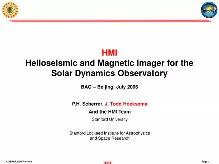
HMI Helioseismic and Magnetic Imager for the Solar Dynamics Observatory BAO – Beijing, July 2006. Outline. The SDO Mission Instrument Overview Calibration Activities HMI Science Goals Observations & Observables Joint Science Operations Center. The Science of SDO. SDO Science Requirements.

E N D
HMIHelioseismic and Magnetic Imager for theSolar Dynamics ObservatoryBAO – Beijing, July 2006
Outline • The SDO Mission • Instrument Overview • Calibration Activities • HMI Science Goals • Observations & Observables • Joint Science Operations Center
SDO Science Requirements • What mechanisms drive the quasi-periodic 11-year cycle of solar activity? • How is active region magnetic flux synthesized, concentrated & dispersed across the solar surface? • How does magnetic reconnection on small scales reorganize the large-scale field topology and current systems? • How significant is it in heating the corona and accelerating the solar wind? • Where do the observed variations in the Sun’s total & spectral irradiance arise, how do they relate to the magnetic activity cycle? • What magnetic field configurations lead to CMEs, filament eruptions and flares which produce energetic particles and radiation? • Can the structure & dynamics of the solar wind near Earth be determined from the magnetic field configuration & atmospheric structure near the solar surface? • When will activity occur and is it possible to make accurate and reliable forecasts of space weather and climate?
Sensing the Sun from Space • High-resolution Spectroscopy for Helioseismology and Magnetic Fields • Observe ripples and polarization properties on the surface of the Sun • Sound waves require long strings of continuous data to interpret—satellites may have no day/night cycle • Convection zone velocities and magnetic fields require high spatial resolution • Coronal Imaging • Observe bright plasma in the corona at ultraviolet wavelengths —can’t be seen from ground • Temperatures of the plasma range from 50,000 K to >3 million K • High spatial resolution to see the detailed interaction of the magnetic field and the plasma • High time resolution is required to see how those features develop • Spectral Irradiance • Measure the total energy in narrow wavelength bands • Measure from space to avoid the twinkling and absorption of atmosphere • Essential for models of the ionosphere • Coronagraphs • Light scattered from the corona and solar wind • Track material as it exits the Sun and moves through the solar system • Energetic Particles and Fields • Point measurements from many platforms to resolve structure
The SDO MissionNASA/LWS Cornerstone Solar Mission • NASA and three Instrument Teams are building SDO • NASA/ Goddard Space Flight Center: build spacecraft, integrate the instruments, provide launch and mission operations • Lockheed Martin & Stanford University: AIA & HMI • LASP/University of Colorado: EVE • Launch is planned for August 2008 on an Atlas V EELV from Cape Canaveral • SDO will be placed into an inclined geosynchronous orbit ~36,000 km (21,000 mi) over New Mexico for a 5-year mission • Data downlink rate is 150 Mbps, 24 hours/day, 7 days/week (1 CD of data every 36 seconds) • Data is sent to the instrument teams and served to the public from there • The primary goal of the SDO mission is to understand, driving towards a predictive capability, the solar variations that influence life on Earth and humanity’s technological systems by determining: • How the Sun’s magnetic field is generated and structured • How this stored magnetic energy is converted and released into the heliosphere and geospace in the form of solar wind, energetic particles, and variations in the solar irradiance. Atlas V carries Rainbow 1 into orbit, July 2003.
The SDO Spacecraft EVE (looking at CCD radiator and front) AIA (1 of 4 telescopes) The total mass of the spacecraft at launch is 3200 kg (payload 270 kg; fuel 1400 kg). Its overall length along the sun-pointing axis is 4.5 m, and each side is 2.22 m. The span of the extended solar panels is 6.25 m. Total available power is 1450 W from 6.5 m2 of solar arrays (efficiency of 16%). The high-gain antennas rotate once each orbit to follow the Earth. High-gain antennas (1 of 2) HMI (looking down from top)
EUV Variability Experiment • EVE is the Extreme ultraviolet Variability Experiment • Built by the Laboratory for Atmospheric and Space Physics at the University of Colorado in Boulder, CO • Data will include • Spectral irradiance of the Sun • Wavelength coverage 0.1-105 nm • Photodiodes to give activity indices • Full spectrum every 20 s • Information needed to drive models of the ionosphere • Cause of this radiation • Effects on planetary atmospheres
SDO Operations • Mission operations for SDO are at NASA's Goddard Space Flight Center near Washington, DC. • Communications with the spacecraft are via two radio dishes at NASA's site in the White Sands Missile Range in New Mexico. • The main tasks of the controllers are to keep SDO pointing at the Sun, maintain its inclined geosynchronous orbit, and keep the data flowing. • A scientific team, led by NASA and instrument project scientists, plans and executes programs of observations with SDO’s 3 instruments suites, and analyzes the data. • Unique Operations Mode • Few observing modes: turn it on and let the data flow! • Raw images are sent to the ground for processing • Data is made available soon after downlink; people can use the data in near-real-time • Campaigns and collaborations are coordinated where convenient, but the data is always available TDRSS antennae in White Sands Missile Range
Mission Orbit Overview • The SDO geosynchronous orbit will result in two eclipse seasons with a variable daily eclipse each day • The two eclipse seasons will occur each year • During each eclipse season, SDO will move through the earth’s shadow- this shadow period will grow to a maximum of ~72 minutes per day, then subside accordingly as the earth-sun geometry moves out of the SDO eclipse season • Eclipse season effects: • Instrument • Interruption to SDO science collection • Thermal impacts to instrument optical system due to eclipse • Power • Temporary reduction or loss of power from solar arrays • Battery sizing includes eclipse impact • Thermal • S/C thermal design considerations due to bi-annual eclipses
Helioseismic & Magnetic Imager • HMI is the Helioseismic and Magnetic Imager • Built at Stanford University and Lockheed Martin in Palo Alto, CA • Two 4096 x 4096 CCDs • Instrument is designed to observe polarized light to measure the magnetic field
HMI Overview • The primary goal of the Helioseismic and Magnetic Imager (HMI) investigation is to study the origin of solar variability and to characterize and understand the Sun’s interior and the various components of magnetic activity. • HMI makes measurements of several quantities • Doppler Velocity (13m/s rms.). • Line-of-sight (10G rms.) and vector magnetic field. • Intensity • All variables all the time with 0.5” pixels. • Most at 50s or better cadence. • Variables are made from filtergrams, all of which are downlinked. • Higher level products will be made as part of the investigation. • All data available to all. • Launch in August 2008. 5 Year nominal mission. • Education and Public Outreach program included!
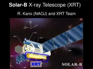
Instrument Overview • Optics package • Telescope section • Polarization selectors – 3 rotating waveplates for redundancy • Focus blocks • Image stabilization system • 5 element Lyot filter. One element tuned by rotating waveplate • 2 Michelson interferometers. Tunable with 2 waveplates and 1 polarizer for redundancy • Reimaging optics and beam distribution system • Shutters • 2 functionally identical CCD cameras • Electronics package • Cable harness
¼ Waveplate ½ Waveplates Image stabilization mirror Beam control lens Aperture stop Blocking filter Telescope lens set Wideband Michelson Telecentric lens Lyot Polarizer Tuning waveplates Calibration lenses and focus blocks Narrowband Michelson ISS beamsplitter and limb tracker assembly BDS beamsplitter Front window filter Relay lens set CCD Shutter assemblies CCD CCD fold mirror Fold mirror CCD fold mirror Instrument Overview – Optical Path Filter characteristics: Central wavelength: 613.7 nm FeI Front window rejects 99% solar heat load Final filter bandwidth: 0.0076 nm Tuning range: 0.069 nm All polarization states measurable Optical characteristics: Focal length: 495 cm Focal ratio: f/35.2 Final image scale: 24m/arcsec = 0.5”/pixel Primary to secondary image magnification: 2 Focus adjustment aange: 16 steps of 0.4 mm
Instrument Overview – HMI Optics Package (HOP) Connector Panel Z Focal Plane B/S Fold Mirror Shutters Alignment Mech X Limb Sensor Y Oven Structure Detector Michelson Interf. Lyot Filter CEBs Detector Vents Limb B/S Front Window Active Mirror Polarization Selector Focus/Calibration Wheels OP Structure Mechanical Characteristics: Box: 0.84 x 0.55 x 0.16 m Over All: 1.19 x 0.83 x 0.29 m Mass: 39.25 kg First Mode: 63 Hz Telescope Support Legs (6) Front Door
Internal Harness (Flight, not complete) Shutters (Flight) BDS Fold Mirror (Flight) Alignment Mechanism (Flight, hidden in view) BDS Beamsplitter (Flight, hidden by shutter) Oven Assembly (non-flight) Parts to replace: E1 and E2 in Lyot NB Michelson Painted housing CCD Fold Mirror (Flight, hidden by detector) Detector Assembly (Non-Flight) Oven Controller (ETU) Flex-Cables (Eng Model) ISS Beam Splitter (Flight) CEB (Non-Flight, DM1) ISS Mirror (Flight) Limb Sensor (Non-Flight) Polarization Selector (Flight) Limb Pre-amp Box (Flight, not complete) Focus/Cal Wheels (Flight) Telescope (Flight) Structure W/ legs and heaters (Flight) Front Window (Flight) Optics Package Assembly • Primary work after Sun testing: • Bond optics in place • Replace painted parts (including the oven) • Replace one HCM and focus/cal optical mounts HMI Assembly Status
Status - Michelsons Michelson ETU
HMI Assembly Status Feb Apr May Mar Structural model testing completed Received flight Michelsons All flight optics in house ETU oven testing completed BB HEB fabrication completed SUROM acceptance test completed mission CDR Jun Aug Jul Hollow core motors completed Received DM cameras Received 4 grade zero CCDs Received flight structure Start alignment on GSE bench Received flight metering tube Completed telescope alignment Nov Oct Sep Dec Alignment mechanism completed Started optical alignment of HOP Focal plane completed Oven completed First image BB HEB and EGSE ready Shutter & F/C wheels completed Internal harness completed Lyot completed Internal mechanisms tested
Status - Cameras Image of CCD Image with CCD
“HMI is Alive” First Image “Special Target” First Lamp Image “Ready to Test” Instrument All Together “No More Moon” Better Laser Image “It’s a Beautiful Day” First Sun Image Laser dot Before holiday No relay lens No Lyot No frt Window Special target Lamp - stim tel Lyot installed Temp mnt for relay lens Not fully aligned stim tel Air Force target Lamp - stim tel All together Laser intensity improved Just sunlight With air/vac corrector 12/22/06 01/11/06 01/25/06 02/01/06 01/30/06 HMI Testing Progress Tests Performed: Initial set up w/ lamp Focus test w/ lamp Distortion, field curvature and MTF w/ lamp Focus test w/ Sun Filter wavelength dependence w/ Sun Tests In Progress: Filter wavelength dependence w/ laser Field curvature and MTF w/ Sun Polarization calibration w/ Sun
Status • Instrument is almost complete • Only one non-flight Camera installed • No CIF and DCHRI boards installed • No radiators • No heaters and thermistors • No vents • No front door • Non flight cover • ISS still being worked • Many items need to be mounted permanently • Except, perhaps, for one of the Michelson all optics are flight • In-Air and vacuum calibrations later this summer • Delivery in March 2007 • Launch in August 2008
Upcoming Tests • Suntest2 • Mostly repeat what was done in first suntest • Verify that instrument has been properly reassembled • Check for gross errors • Check that earlier problems have been corrected • Eg. Birefringence in focus block • Provide data to adjust various components • Eg. Calmode lenses, waveplate rotation, CCDs, … • Check software • Must be in good shape before actual calibrations • In-air calibration • Gather actual calibration data • Some, such as part of polarization may not be doable in vacuum • Vacuum calibration • Repeat most in-air calibrations with lower noise • Some items only doable in vacuum (E.g. Noise tests)
Sun Test Objectives • Learn how to operate the HMI optics package. • Learn how to characterize/calibrate the instrument. • Discover gross errors in design or workmanship of the HMI optics package. • Determine position of focus to set the final shim on the secondary lens. • Determine position of waveplates in polarization selector to set the final orientation relative to hollow core motor step locations. • Results of the Sun test will directly feed into the plans and procedures for the formal test and calibration series. • The Sun test does not provide formal verification of any requirements. • The Sun test does not provide final calibration data. • The instrument had not been finally assembled during first Sun test. • Several components were missing. • Several components have since been changed. • Test setup was under development. • Test procedures and analysis software were under development.
Image Quality • Distortion • Image scale • MTF • Focus and field curvature • Ghost images and scattered light • Contamination • Image motions
HMI Testing Progress First Dopplergram First Magnetogram
Primary goal: origin of solar variability • The primary goal of the Helioseismic and Magnetic Imager (HMI) investigation is to study the origin of solar variability and to characterize and understand the Sun’s interior and the various components of magnetic activity. • HMI produces data to determine the interior sources and mechanisms of solar variability and how the physical processes inside the Sun are related to surface and coronal magnetic fields and activity.
HMI Science Objectives • HMI science objectives are grouped into five broad categories: • Convection-zone dynamics • How does the solar cycle work? • Origin and evolution of sunspots, active regions and complexes of activity • What drives the evolution of spots and active regions? • Sources and drivers of solar activity and disturbances • How and why is magnetic complexity expressed as activity? • Links between the internal processes and dynamics of the corona and heliosphere • What are the large scale links between the important domains? • Precursors of solar disturbances for space-weather forecasts • What are the prospects for prediction? • These objectives are divided into 18 sub-objectives each of which needs data from multiple HMI data products.
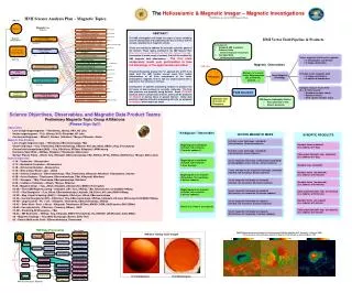
B – Rotation Variations J – Subsurface flows C – Global Circulation I – Magnetic Connectivity A – Interior Structure D – Irradiance Sources E – Coronal Magnetic Field H – Far-side Imaging F – Solar Subsurface Weather G – Magnetic Fields HMI Data Product Examples • Sound speed variations relative to a standard solar model. • Solar cycle variations in the sub-photospheric rotation rate. • Solar meridional circulation and differential rotation. • Sunspots and plage contribute to solar irradiance variation. • MHD model of the magnetic structure of the corona. • Synoptic map of the subsurface flows at a depth of 7 Mm. • EIT image and magnetic field lines computed from the photospheric field. • Active regions on the far side of the sun detected with helioseismology. • Vector field image showing the magnetic connectivity in sunspots. • Sound speed variations and flows in an emerging active region.
HMI Science Objectives • Convection-zone dynamics and the solar dynamo • Structure and dynamics of the tachocline • Variations in differential rotation • Evolution of meridional circulation • Dynamics in the near surface shear layer • Origin and evolution of sunspots, active regions and complexes of activity • Formation and deep structure of magnetic complexes of activity • Active region source and evolution • Magnetic flux concentration in sunspots • Sources and mechanisms of solar irradiance variations • Sources and drivers of solar activity and disturbances • Origin and dynamics of magnetic sheared structures and d-type sunspots • Magnetic configuration and mechanisms of solar flares • Emergence of magnetic flux and solar transient events • Evolution of small-scale structures and magnetic carpet • Links between the internal processes and dynamics of the corona and heliosphere • Complexity and energetics of the solar corona • Large-scale coronal field estimates • Coronal magnetic structure and solar wind • Precursors of solar disturbances for space-weather forecasts • Far-side imaging and activity index • Predicting emergence of active regions by helioseismic imaging • Determination of magnetic cloud Bs events
Doppler Velocity Line-of-sight Magnetograms Vector Magnetograms Continuum Brightness HMI Science Analysis Plan HMI Data Processing Data Product Science Objective Tachocline Global Helioseismology Processing Internal rotation Ω(r,Θ) (0<r<R) Meridional Circulation Filtergrams Internal sound speed, cs(r,Θ) (0<r<R) Differential Rotation Near-Surface Shear Layer Full-disk velocity, v(r,Θ,Φ), And sound speed, cs(r,Θ,Φ), Maps (0-30Mm) Local Helioseismology Processing Activity Complexes Active Regions Carrington synoptic v and cs maps (0-30Mm) Sunspots Irradiance Variations High-resolution v and cs maps (0-30Mm) Observables Magnetic Shear Deep-focus v and cs maps (0-200Mm) Flare Magnetic Configuration Flux Emergence Far-side activity index Magnetic Carpet Line-of-Sight Magnetic Field Maps Coronal energetics Large-scale Coronal Fields Vector Magnetic Field Maps Solar Wind Coronal magnetic Field Extrapolations Far-side Activity Evolution Predicting A-R Emergence Coronal and Solar wind models IMF Bs Events Version 1.0w Brightness Images
7 Sun dynamo 6 polar field Rings Global HS Zonal flow 5 AR Time-Distance P-modes spot Earth SG 4 granule 3 Log Size (km) HMI resolution 2 7 1 2 3 6 4 5 8 9 10 min day year hour 5min cycle Log Time (s) Solar Domain of HMI Helioseismology rotation
7 Coronal field estimates Sun dynamo 6 polar field Large-Scale 5 Vector AR P-modes spot Earth SG 4 Line-of-sight Granule 3 Log Size (km) HMI resolution 2 7 1 2 3 6 4 5 8 9 10 min day year hour 5min cycle rotation Log Time (s) Solar Domain of HMI Magnetic Field
Key Features of HMI Science Plan • Data analysis pipeline: standard helioseismology and magnetic field analyses • Development of new approaches to data analysis • Targeted theoretical and numerical modeling • Focused data analysis and science working groups • Joint investigations with AIA and EVE • Cooperation with other space- and ground-based projects (SOHO, Solar-B, PICARD, STEREO, RHESSI, GONG+, SOLIS, etc)
Observing Scheme • Observables • Dopplergrams • Magnetograms, vector and line-of-sight • Others: Intensity, line depth, etc. • Observables made from filtergrams described by framelists • Filtergram properties • Wavelength – selected by rotating waveplates (polarizer for redundancy only) • Polarization state – selected by rotating waveplates • Exposure time • Camera ID • Compression parameters, … • Determined by subsystem settings • E.g. motor positions • Framelists • List of filtergrams repeated at fixed cadence during normal operations • Entirely specified in software – Highly flexible
Framelist Example • Time: Time of first exposure at given wavelength since start of framelist execution • Tuning: I1, I2, … specify the tuning position • Doppler pol.: Polarization of image taken with Doppler camera • L and R indicate left and right circular polarization • Used for Doppler and line of sight field • Vector pol.: Polarization of image taken with vector camera • 1, 2, 3, 4: Mixed polarizations needed to make vector magnetograms • Used for vector field reconstruction • Note that the data from the two cameras may be combined
Observables Calculation • Make I, Q, U, V, LCP, RCP • Linear combinations of filtergrams • Correct for flat field, exposure time and polarization leakage • Correct for solar rotation and jitter (spatial interpolation) • Sun rotates by 0.3 pixels in 50s, so interpolation necessary • Fast and accurate algorithm exists • Correct for acceleration effects (temporal interpolation) • Nyquist criterion almost fulfilled for Doppler and LOS but is violated for vector measurements • Significant improvement from interpolation and averaging • Fill gaps • Data loss budget gives missing data in every filtergram, various algorithms exist • May do nothing for vector field • Calculate observables • MDI-like and/or least squares for Doppler and LOS • Fast and/or full inversion for vector field • Many challenges remain • Calibration, code development, lists of dataproducts etc. • Community input needed!
Internal rotation Ω(r,Θ) (0<r<R) Processing Data Product Internal sound speed, cs(r,Θ) (0<r<R) HMI Data Spherical Harmonic Time series To l=1000 Heliographic Doppler velocity maps Filtergrams Mode frequencies And splitting Full-disk velocity, v(r,Θ,Φ), And sound speed, cs(r,Θ,Φ), Maps (0-30Mm) Carrington synoptic v and cs maps (0-30Mm) Local wave frequency shifts Ring diagrams Doppler Velocity High-resolution v and cs maps (0-30Mm) Time-distance Cross-covariance function Tracked Tiles Of Dopplergrams Wave travel times Deep-focus v and cs maps (0-200Mm) Egression and Ingression maps Wave phase shift maps Far-side activity index Stokes I,V Line-of-sight Magnetograms Line-of-Sight Magnetic Field Maps Stokes I,Q,U,V Full-disk 10-min Averaged maps Vector Magnetograms Fast algorithm Vector Magnetic Field Maps Coronal magnetic Field Extrapolations Vector Magnetograms Inversion algorithm Tracked Tiles Tracked full-disk 1-hour averaged Continuum maps Coronal and Solar wind models Continuum Brightness Solar limb parameters Brightness feature maps Brightness Images HMI Data Analysis Pipeline HMI Data Processing and Products Level-0 Level-1
Joint HMI/AIA SOC • Common aspects • Instrument commanding • Telemetry data capture (MOC to JSOC and DDS to JSOC interfaces) • Pipeline generation of Level-1 data • Distribution of data to co-investigator teams and beyond • Location of facilities • Unique requirements • HMI Higher Level Helioseismology Data Products • AIA Visualization and Solar Event Catalog
JSOC Scope • The HMI/AIA Joint SOC consists of two parts: • Science Data Processing (SDP) – at Stanford and LMSAL • Joint Operations Center (JOC) – at LMSAL • JSOC JOC includes: • HMI and AIA Commanding and Health Monitoring • HMI and AIA Engineering support as needed • JSOC SDP includes: • HMI and AIA Telemetry Data capture (from DDS) and archive • HMI and AIA Level-0 processing and archive • HMI processing through to level-2 with archiving of end products • AIA processing through level-1a with online archive at Stanford • AIA level-2 processing at LMSAL • Data export of the above and other HMI and AIA products as needed • JSOC does not include tasks such as: • Science analysis beyond level-2 products • HMI and AIA EPO • HMI & AIA Co-I science support
Tracking Data Space Network (L&EO only) Acquisition Data S-Band: TRK & HK Tlm S-Band HK Tlm CMD S-Band: TRK, Cmd & HK Tlm Tracking Data SDO Ground Station STGT S-Band HK Tlm Universal Space Network S-Band: TRK, Cmd & HK Tlm SDO S-Band RF & FEP system CMD, Acquisition Data (Includes 72-hr storage) Ka-Band: 150 Mbps Science Data DDS FEP Same Interfaces Ka-Band RF system Tracking Data as WSGT Ground Station (Incl. 120-hr storage) OD Products S-Band: TRK, Cmd & HK Tlm Ka-Band: 150 Mbps Science Data SDO Ground Station WSGT SDO Mission Operations Center Observatory Commands Acquisition Data S-Band RF & Flight Dynamics Telemetry & Command System FEP system Observatory HK Telemetry System (Includes 72-hr storage) DDS FEP Tracking Data Maneuver Planning Mini MOC Ka-Band RF system Product Generation ASIST / FEDS (Incl. 120-hr storage) R/T Attitude Determination Status and Control Telemetry Monitoring Sensor/Actuator Calibration Command Management Flight Dynamics Facility HK Data Archival HK Level-0 Processing Ka Science Data Ka Science Data Mission Planning & Scheduling Orbit Determination Product Generation DDS & SDOGS Integrated Manager Data Distribution System Station/DDS Control Ground Station Control DDS Control Plan daily/periodic events Status and Control Station/DDS Status Create engineering plan (Incl. 30-Day Science Data Storage) Generate Daily Loads Automated Operations Anomaly detection DDS & Ground Station Control Integrated Trending & Plotting System WSC Data Ack. & Retrans. Requests Data Ack. & Retrans. Requests Alert Notification System AIA Science Data (67Mbps) HMI Science Data (55Mbps) EVE Science Data (7Mbps) Stanford Univ. EVE SOC (Stanford, CA) LASP (Boulder, CO) Science Data Capture Instrument Monitoring & Control Flight software loads Simulated housekeeping telemetry Science Data Capture S/C Memory dumps Simulated commands HMI AIA JSOC LMSAL Flight Software Maintenance Lab (Palo Alto, CA) Instrument Monitoring & Control EVE R/T HK Telemetry Science Planning and FDS Products FSW Support Tool Suite Instrument Commands/Loads Instrument Commands/Loads AIA R/T HK Telemetry/ Science Planning and FDS Products GSFC Instrument Commands/Loads HMI R/T HK Telemetry/ Science Planning and FDS Products FLATSAT 10/21/03 SDO Ground System Architecture