Download
1 / 58
600 likes | 996 Vues
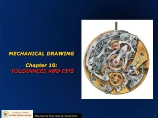
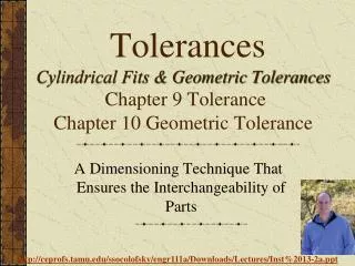
Tolerances Cylindrical Fits & Geometric Tolerances Chapter 9 Tolerance Chapter 10 Geometric Tolerance. A Dimensioning Technique That Ensures the Interchangeability of Parts. http://ceprofs.tamu.edu/ssocolofsky/engr111a/Downloads/Lectures/Inst%2013-2a.ppt. So I found these slides….

E N D
TolerancesCylindrical Fits & Geometric TolerancesChapter 9 ToleranceChapter 10 Geometric Tolerance A Dimensioning Technique That Ensures the Interchangeability of Parts http://ceprofs.tamu.edu/ssocolofsky/engr111a/Downloads/Lectures/Inst%2013-2a.ppt
So I found these slides… TolerancesCylindrical Fits & Geometric TolerancesENGR 111 13.2a LockheedSR 71
LockheedSR 71 SPECIFICATIONS: Span: 55 ft. 7 in. Length 101 ft Height: 18 ft. 6 in Wt. 127,000 lbs (full load) Records set May 1st 1965…… Speed 2070.101 mph Altitude 80,257.86 ft.
LockheedSR 71 From the 1960’s on, the SR-71 was the hottest thing in the air. Literally. “When we landed, the maintenance guys were real careful not to touch the plane”, says Ken Collins, an Air Force Colonel who flew the plane faster than Mach 3 (2280 mph). Air friction pushed the temperature of the canopy to around 600F. From the heat expansion the airplane grew several inches in flight.
Learning Objectives • Apply linear tolerances in both the English and Metric systems (applied to holes and shafts) • Calculate the following parameters, given a dimensioned set of mating parts: Allowance, Clearance, Hole Tolerance, Shaft Tolerance. • Match Geometric Tolerance symbols with their meaning. • Apply Geometric tolerances with AutoCAD.
But first, some corrections from last week… • Adjusting the size of individual dimension parts (arrows, gaps, etc) is not necessary: • Choose dimension styles>modify>fit … • Change just the overall scale factor! It changes all parts at same time
How to have multiple tolerance styles • Dimension Styles>New • Name it: normal 2dec_dev02_01 • Go in and set Tolerance precision .00 • Deviation upper .02 lower .01 • Make all kinds of dimension styles, select using pull down menu
Tables Special layouts can be done manually using rectangles, text command, copy, etc Array command can extend rows
Table Command • Type Table, then choose number of rows, columns, etc. • Easy to insert text • Can stretch or shrink table • May not conform to unique layout needs • Text size can be modified • Shift click all boxes • R-click>Properties text height
Tolerance ??? • The Oxford English dictionary defines tolerance as: b. In Mech., an allowable amount of variation in the dimensions of a machine or part. More widely, the allowable amount of variation in any specified quantity Or, paraphrased… “Tolerance is how accepting of errors you are”.
General Concepts • A measurement with a zero tolerance is impossible to manufacture in the real world. • Tolerances on parts contribute to the expense of a part, the smaller the tolerance the more expensive the part.
Types of Tolerances • General Tolerances –Limit the error a machinist is allowed on all dimensions, unless otherwise specified • Linear Tolerances –Specific error limits for a particular linear measurement. • Geometric Tolerances– Errorlimits, not on the size, but on the shape of a feature.
General Tolerance • Are specified in the title block of a drawing. • Must always be included on “real” parts. .
Linear Tolerance • Is an overriding tolerance which specifies a tolerance for one specific dimension. • Can be listed in limit or deviation form, but normally should be specified on an engineering drawing in limit form. • Should only be used in the case of real necessity, not just because. • ?? WHY ???
Example of Linear Tolerance • The parts shown to the right illustrates a linear tolerance shown in limit form.
“Forms” of Linear Tolerance • Unilateral. Variation in one direction • Bilateral. Variation in two directions • Limit. Max & Min.. largest on top
Terminology: • There are four parameters of interest: • Hole Tolerance. • Shaft Tolerance. • Allowance. • Maximum Clearance.
Hole Tolerance • The difference between the diameters of the largest and smallest possible holes. • Determines the cost of manufacturing the hole. • Does not consider the Shaft at all.
Shaft Tolerance • The difference between the diameters of the largest and smallest possible shafts. • Determines the cost of the shaft. • Does not consider the Hole at all.
Allowance • The tightest fit between two mating parts. • Determines how the two parts will interact with one another. • Smallest hole minus largest shaft. • Or the “gap” between smallest hole & largest shaft. • Does not affect the cost of the parts.
Maximum Clearance • The loosest fit between mating parts. • Determines how the two parts will interact with one another. • Largest hole minus smallest shaft. • Or the “gap” between largest hole hole & smallest shaft. • Does not affect the cost of the parts.
Formulas for calculation • Hole Tolerance = LH - SH • Shaft Tolerance = LS - SS • Allowance = SH - LS • Maximum Clearance = LH - SS LH=Large Hole, SH=Small Hole LS-Large Shaft, SS=Small Shaft
Other definitions • Nominal Size - The approximate size of a part. • Actual Size - The measured size of a finished part. • Basic Size - The exact theoretical size for a part, used to calculate the acceptable limits. • Hole Basis - A system of fits based on the minimum hole size as the basic diameter.
Practical Application • This class is not trying to teach the design aspect of tolerance • We will be interested in applying a given tolerance to a part, not in determining the “best” tolerance • Various industries (aerospace, electronics, automotive, etc.) set their own tolerances.
Types of Fits • Linear tolerances can be classified in 4 major categories, based on the interaction between the parts : • Clearance Fit. • Line Fit. • Transition Fit. • Interference Fit (Force Fit).
English Example • Running and sliding fit RC9 • Basic diameter 2.00” • Hole limits +7.0, 0 • Shaft limits -9.0, -13.5 • Max Clear ???? • Allowance ???? • Hole Tolerance. ???? • Shaft Tolerance ????
English Example Note that all values are listed in thousandths of an inch. See your textbook’s Appendix p744 - 747
English Example • Running and sliding fit RC9 • Basic diameter 2.00” • Hole limits +7.0, 0 • Shaft limits -9.0, -13.5 • Max Clear .0205 • Allowance .0090 • Hole Tolerance .0070 • Shaft Tolerance .0045
Clearance Fit • In a clearance fit, the two parts will always fit together with room to spare
Clearance Fit • In a clearance fit, the two parts will always fit together with room to spare • As a team, calculate the: Hole Tolerance.______ Shaft Tolerance.______ Allowance.__________ Clearance. __________ for the fit shown …
Clearance Fit • In a clearance fit, the two parts will always fit together with room to spare • As a team, calculate the: Hole Tolerance. .0007 Shaft Tolerance. .0004 Allowance. .0006 Clearance. .0017
Line Fit • In a line fit, the two parts may fit together with no room to spare
Line Fit • In a line fit, the two parts may fit together with no room to spare • As a team, calculate the: Hole Tolerance._____ Shaft Tolerance._____ Allowance. _________ Clearance. _________ for the fit shown ……
Line Fit • In a line fit, the two parts may fit together with no room to spare • As a team, calculate the: Hole Tolerance. .0007 Shaft Tolerance. .0010 Allowance. 0 Clearance. .0017
Transition Fit • In a transition fit, the two parts may either clear or interfere with each other…probably the cheapest way to manufacture products. Used with selective assembly process
Transition Fit • In a transition fit, the two parts may either clear or interfere with each other • As a team, calculate the: Hole Tolerance._____ Shaft Tolerance._____ Allowance._________ Clearance.__________ for the fit shown to the right. …………….
Transition Fit • In a transition fit, the two parts may either clear or interfere with each other • As a team, calculate the: Hole Tolerance. .045 Shaft Tolerance. .051 Allowance. -.037 Clearance. -.059
Interference Fit • In an interference fit, the two parts will always interfere with each other, requiring a force or press fit
Interference Fit • In an interference fit, the two parts will always interfere with each other, requiring a force or press fit • As pairs, calculate the Hole Tolerance.________ Shaft Tolerance.________ Allowance.____________ Clearance._____________ for the fit shown to the right. ………………
Interference Fit • In an interference fit, the two parts will always interfere with each other, requiring a force or press fit • As pairs, calculate the Hole Tolerance. .013 Shaft Tolerance. .016 Allowance. -.037 Clearance. -.008
English Fits • ANSI standards list five type of fits: • RC: Running and Sliding Clearance Fits • LC: Clearance Locational Fits • LT: Transition Locational Fits • LN: Interference Locational Fits • FN: Force and Shrink Fits • Each of these has several classes (Appendix A) • The higher the class number, the greater the tolerance and the looser the fit.
Metric Fits See Appendix p748-751 Clearance Fits Transition Interference
Metric Example • H11/c11 (loose running) • Basic diameter 40 mm • Hole size 40.160,40.000 • Shaft size 39.880,39.720 • Max Clear ???? • Allowance ???? • Hole Tolerance ???? • Shaft Tolerance ????
Metric Example • H11/c11 (loose running) • Basic diameter 40 mm • Hole size 40.160,40.000 • Shaft size 39.880,39.720 • Max Clear 0.440 • Allowance 0.120 • Hole Tolerance 0.160 • Shaft Tolerance 0.160
Geometric Tolerances (see Ch11) • Geometric tolerancing is a system that specifies tolerances that control location form, profile, orientation, location, and runout on a dimensioned part NOTE: Many standard symbols are Used to represent “Geotol” Relationships…parallel, perpendicular, angular, round, and flat are fairly obvious
Geometric Tolerances See Ch11 • Feature control boxes (call outs) are used to place geometric tolerances in most drawings. Standard letter height is recommended (1/8-in or 3 mm)
Geometric Tolerances L LMC….Least Mat’l Cond. M MMC...Max Mat’l Cond. R RFS…..Regardless of Feature size.
Some terminology • Feature Tolerance—what we’ve been doing • Lengths, angles, diameters, etc • Refers to the error in manufacturing feature • Geometric Tolerance—specs shape variat’n • Flatness of a surface to 0.3 • Straightness of a shaft about it’s centerline • Circularity of a cylinder