Download

1 / 17
170 likes | 298 Vues
Design and Construction of BigBite Platform and Carriages. Ravi Anumagalla. Design Requirements & Procedures. Design the Support Structure for the BigBite Spectrometer Assembly. The Support Structure should accommodate various BigBite Experiments.

E N D
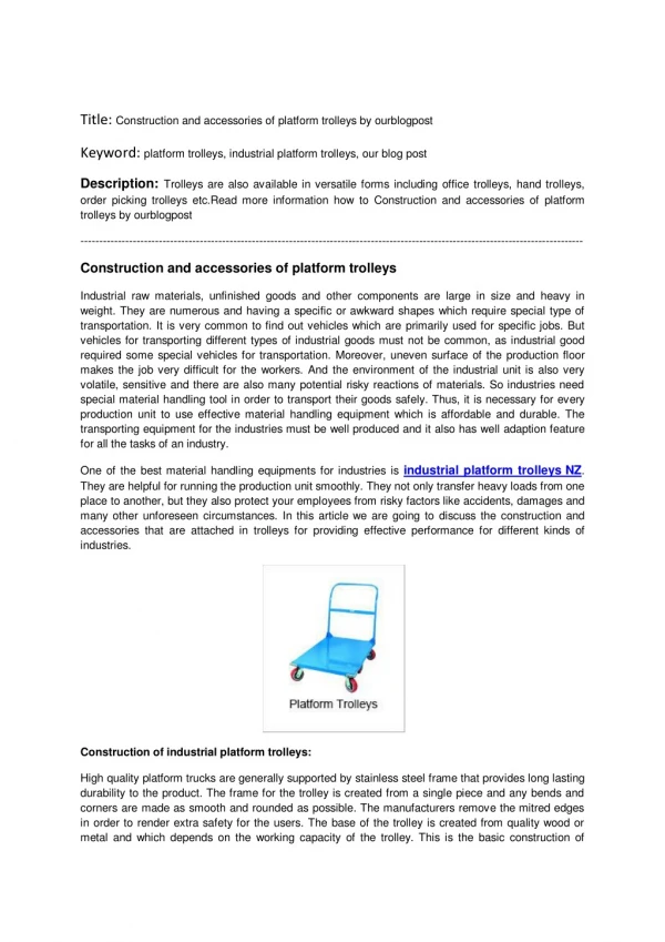
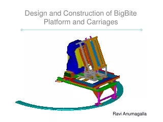
Design and Construction of BigBite Platform and Carriages Ravi Anumagalla
Design Requirements & Procedures • Design the Support Structure for the BigBite Spectrometer Assembly. • The Support Structure should accommodate various BigBite Experiments
The support structures for the BigBite and the detectors are designed to accommodate the individual weights • Rollers are provided for achieving various configurations • Rollers are equipped with necessary cams to guide the motion in the conformed direction • Spacers are provided for the vertical alignment of the various subassemblies • Main Frame : • Spans 14 ft which accommodates the support structures for the BigBite magnet and the detector • Beams and Columns have been selected to endure the total weight • Gussets are welded for uniform stress distribution • Selection of I-beam facilitates path for the rollers and also to accommodate the bending moment due to loading
BigBite Frame • Designed to support the BigBite magnet • Two Single pieces of weldment, ”BigBite Wings” are bolted to the BigBite Magnet • BigBite support structure has been redesigned to avoid cutting of pivot assembly • The Bolt pattern matches with the 25 deg cut of the magnet • Design of the frame has been verified with the Finite Element Solution Spacer
Detector Frame • Frame is supported by 6 rollers to accommodate the detectors for various experiments • Platforms and railings are designed as per “OSHA” standards • Platform is designed for performing maintenance on the detector • Kick plates are provided for safety during maintenance • A Base track of 160 deg is necessary to achieve all configurations. (includes additional 15 deg on each side)
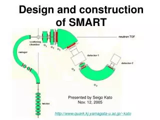
Magnet (20 tons) (40kips) Detector(10 tons) (20kips) 180.5 in Path for the rollers to move
Big Bite Platform Detector Platform Main Frame
Cost Estimation of Big Bite Support Structure • The Weights of the individual Assemblies are as follows : • Main Frame Assy 2515 Lb • Detector Frame Sub Assy 892 Lb • Big Bite Frame Sub Assy 1700 Lb • The cost of Structural steel (A36) is $0.15 per pound. Considering the cost to be $3.5 per lb, Hence the total cost for the Support Structure is • (2515+892+1700) = 5107 Lb X 3.5 = $ 17,874.5 • Rollers cost : 14 X 1000 = $14,000 • Grand Total : $31,874
Roller for Support on both beams required 45.75 4.25 51.875 Roller to be supported
Beam 1(W8X48) Beam2(W6X20) Beam 3(W6X20)