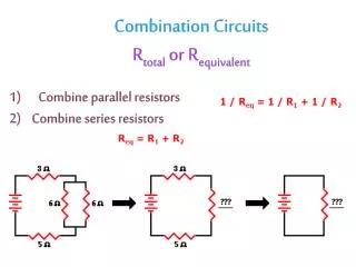
R-L Circuits
R-L Circuits. R-L Circuits? What does the “L” stand for?. Good Question! “ L ” stands for the self-inductance of an inductor measured in Henrys (H). So…What is an inductor? An inductor is an electronic device that is put into a circuit to prevent rapid changes in current.

R-L Circuits
E N D
Presentation Transcript
R-L Circuits?What does the “L” stand for? • Good Question! “L” stands for the self-inductance of an inductor measured in Henrys (H). • So…What is an inductor? • An inductor is an electronic device that is put into a circuit to prevent • rapid changes in current. • It is basically a coil of wire which uses the basic principles of • electromagnetism and Lenz’s Law to store magnetic energy within • the circuit for the purposes of stabilizing the current in that circuit. • The voltage drop across an inductor depends on the inductance value L and the rate of change of the current di/dt.
ε S1 S2 a b L c R R-L CircuitsThe set up and initial conditions An R-L circuit is any circuit that contains both a resistor and an inductor. Assume an ideal source (r=0) At time t = 0, we will close switch S1 to create a series circuit that includes the battery. The current will grow to a “steady-state” constant value at which the device will operate until powered off (i.e. the battery is removed) Initial conditions:At time t = 0…when S1 is closed…i = 0 and
ε S1 S2 i a b L c R R-L CircuitsCurrent Growth Note: we will use lower-case letters to represent time-varying quantities. At time t = 0, S1 is closed, current, i, will grow at a rate that depends on the value of L until it reaches it’s final steady-state value, I If we apply Kirchoff’s Law to this circuit and do a little algebra we get… As “i” increases, “iR/L” also increases, so “di/dt” decreases until it reaches zero. At this time, the current has reached it’s final “steady-state” value “I”.
ε S1 S2 i a b L c R R-L CircuitsSteady-State Current When the current reaches its final “steady-state” value, I, then di/dt = 0. Solving this equation for I… So…when the current is at steady-state, the circuit behaves like the inductor is not there…unless it tries to change current values quickly! The steady-state current does NOT depend on L! Do you recognize this? It is Ohm’s Law!!!
ε S1 S2 i a L b c R R-L CircuitsCurrent as a function of time during GrowthThe calculus and the algebra! Let’s start with the equation we derived earlier from Kirchoff’s Law… Rearrange and integrate… Solve for i…
ε S1 S2 i a L b c R R-L CircuitsThe time constant! The time constant is the time at which the power of the “e” function is “-1”. Therefore, time constant is L/R At time t = 2 time-constants, i = 0.86 I, and at time t = 5 time-constants, i = 0.99995 I Therefore, after approximately 5 time-constant intervals have passed, the circuit reaches its steady-state current.
ε S1 S2 i a L b c R R-L CircuitsEnergy and Power