Pulsed and Square Wave Voltammetry Techniques: A Comprehensive Overview
Explore the evolution and applications of pulsed and square wave voltammetry methods from 1950s to modern times, including waveform approximations, key principles, and detection limits.

Pulsed and Square Wave Voltammetry Techniques: A Comprehensive Overview
E N D
Presentation Transcript
Pulsed and square wave voltammetry Inventor: Sir Geoffrey Barker, Harwell, UK 1950-60s Modern versions. Janet and Robert Osteryoung, Univ. Colorado/SUNY Buffalo
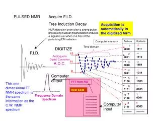
Digital voltammetry waveforms – staircase used to approximate a ramp for LSV; All modern potentiostats use this approach, also easy to use other input waveforms All sorts of pulsed voltammetry methods were developed in 1950-60s by Sir Geoffrey Barker in UK, and later 1970-80s modernized by Janet and Bob Osteryoung in the US
Basis of all pulsed methods: Response of reversible system to a potential pulse; Measuemenst at end of pulse discriminates against charging current E 60 ms time measurement Faradaic I Charging (decays faster)
Normal Pulsed Voltammetry (simplest) DL about 10-fold lower than cyclic voltammetry (CV) Input waveform output I = IL/(1+θ) θ = {nf/RT)(E-Eo’)} IL=nFCo*AD1/2/(πt)1/2
Input waveforms output Normal pulse voltammetry Differential Pulse voltammetry Ep nM detection limits
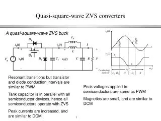
Square Wave Voltammetry – complex waveform, derivative output most sensitive instrumental electrochemical method Input waveform Ip= f(Co*, ΔE) Ep= E1/2 – ΔE/2 output Ep nM detection limits; Slightly better than Differential pulse
SWV outputs Net or difference current Forward Current Reverse current
NPV SWV difference current I x 1000 O1 + e == R1 R1 + e == R2 Better resolution, Best sensitivity
SWV Output Net or difference current forward reverse
SWV parameters - increasing frequency (effect of DE is similar)
Approx DL NPV 10-6 M/n DPV 2x10⁻⁹ M/n SCV or LSV (CV) 5x10⁻⁵ M/n SWV 10-9 M/n