Advanced Endpoint Detection for Shallow Etching Using Interferometric Signal Analysis
This research presents a cutting-edge approach for etch process control without a stop layer, utilizing an interferometric endpoint system. The method combines the full Optical Emission Spectrum (OES) and Interferometric Endpoint (IEP) spectra to enhance depth monitoring, achieving improved signal clarity and reduced noise. Employing a PCA-based method, the spectrums are decomposed into independent signals, facilitating reliable depth control in high-volume production environments. Results demonstrate significant advancements in endpoint detection accuracy during shallow recess etching.

Advanced Endpoint Detection for Shallow Etching Using Interferometric Signal Analysis
E N D
Presentation Transcript
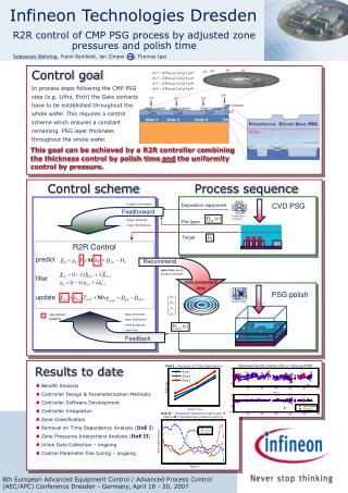
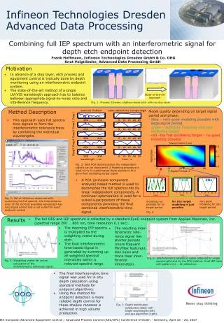
Motivation • In absence of a stop layer, etch process and equipment control is typically done by depth monitoring using an interferometric endpoint system. • The state-of-the-art method of a single UV/VIS wavelength approach has to balance between appropriate signal-to-noise ratio and interference frequency. State-of-the-Art Approach Fig. 1: Process Scheme, shallow recess etch with no stop layer. Results • The full OES and IEP spectrum is collected by a standard EyeD endpoint system from Applied Materials, Inc. (spectral range 200 … 800 nm, time resolution 0.1 sec). • The incoming IEP spectra is multiplied by the weighting vector during etch. • The final interferometric time-based signal is generated by summing up all weighted spectral intensities within a relevant spectral range. • The resulting inter-ferometric refe-rence signal has shorter periods (more frequent Min/Max features), less noise and more clear inter-ference information. red/green:Interferometric reference signal obtained by a typical single wavelength (280/229 nm, smoothing over 5 data points) blue: Interferometric reference signal provided by the pca method (smoothing over 5 data points) Fig. 6: Interferometric reference signal obtained by single wavelengths and by the PCA method. Final IEP trace with pattern (t1 … t4) detection. Fig. 5: Weighting vector for online calculation of the interferometric reference signal. • The final interferometric time signal was used for in situ depth calculation using standard methods for endpoint algorithms. • Using this method for endpoint detection a more reliable depth control for these shallow recesses is achieved in high volume production. Fig. 7: Depth distribution (productive data) with single wavelength (left) and pca algorithm (right). Infineon Technologies DresdenAdvanced Data Processing Combining full IEP spectrum with an interferometric signal for depth etch endpoint detection Frank Hoffmann, Infineon Technologies Dresden GmbH & Co. OHG Knut Voigtländer, Advanced Data Processing GmbH Method Description • Model quality depending on target signal period and phase:- blue – very good modeling possible with large signal period.- green – sufficient modeling with fast oscillating target- red –too fast oscillating target – no good modeling possible • This approach uses full spectra time signals to form the interferometric reference trace by combining the individual wavelengths. Fig. 3: With PCA decomposition the independent signals can be discovered. A Modeling procedure is used to try to superimpose these signals to fit a given fast oscillating target signal. 5s 10s • A PCA (principle component analysis) based method is used to decompose the full spectra into its linear independent components. A nonlinear optimization is used for a suited superposition of these components providing the final combined interferometric time signal. 20s Fig. 2: Set of reference measurements containing the full spectra; the time behavior even of the shortest available wavelength has long signal period and is not suited for exact endpoint control. very good modeling for 20s target period modeling not possible for 5s target period for 10s target modeling is just possible Fig. 4 8th European Advanced Equipment Control / Advanced Process Control (AEC/APC) Conference Dresden - Germany, April 18 - 20, 2007