DISTILLATION CONTROL
DISTILLATION CONTROL. Dr. Prakash Karpe Control & Elec. Eng. Supt. ConocoPhillips San Francisco Refinery, Rodeo. Distillation Column Control Control Objectives. Q c. V. D. L. Rectification Stages. R = L/D. F. Stripping Stages. Q H. B. Two Control objectives Inventory control

DISTILLATION CONTROL
E N D
Presentation Transcript
DISTILLATION CONTROL Dr. Prakash Karpe Control & Elec. Eng. Supt. ConocoPhillips San Francisco Refinery, Rodeo
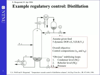
Distillation Column Control Control Objectives Qc V D L Rectification Stages R = L/D F Stripping Stages QH B • Two Control objectives • Inventory control • Composition control
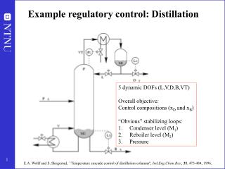
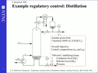
Degrees of Freedom Analysis • From control perspective, degrees of freedom of a process is defined as number of variables that can or must be controlled. • Helps to avoid over- or under-control of processes. • Degrees of freedom (to control) = No. of rationally placed control valves • A control valve represents a manipulated variable (MV)
Degrees of Freedom Analysis Flash Vessel (Separator) V F F,T,P,xi Disturbances B
Inventory Control • For steady state operation of a process, all inventories must be controlled • Vapor inventories are maintained by pressure control • Liquid inventories are maintained by level control
PC LC Degrees of Freedom Analysis Flash Vessel (Separator) Degrees of Freedom = 0 V F F,T,P,xi Disturbances B
Degrees of Freedom Analysis Typical Distillation Column Inventory Control PC V LD L D TD F TB QH LB LC B Degrees of Freedom = 3
Liquid Inventory ControlLevel Control • Reflux drum level control • LD - L or LD – D? • Richardson’s rule: • Use the largest stream to control level. • Guidelines: • L/D < = 1 : Use LD – D pairing • L/D > = 5 : Use LD – L pairing • For 1 < L/D < 5, use scheme proposed by Rysjkamp • (L+D) – D and L/D – L pairings
Two Common Level Control Schemes • Level control dilemma • Tight flow control? • Oscillating level • Tight level control? • Oscillating product flow • Averaging or nonlinear level control • Tight level control
Common Level Control Schemes • Averaging (nonlinear) level control • Used when product is a feed to a downstream process • Examples • Train of lightends columns • Reflux drum level control • Tight level control • Used when product goes to tankage or a surge drum or process requires low hold up • Use P-only controller with KC = 4 • Examples • Reboiler level control • FCC Main Frac and Vacuum column bottoms (coking concern) • Dirty wash oil draw level control • Control hydrostatic P in the draw line
Vapor Inventory ControlCommon Pressure Control SchemesPartial Condensers • Common Problems • If off gas is routed to a compressor, reflux drum P is controlled leading to tower P swings. Off gas rate > 0
Common Pressure Control SchemesPartial Condensers Off gas rate > 0 or = 0 • Common Problems • If off gas is routed to a compressor, reflux drum P is controlled leading to tower P swings. • Inert gas, typically noncondesables, can cause downstream process problems
Common Pressure Control SchemesTotal CondensersFlooded Condenser Off gas rate = 0 • Common Problems • If P equalizing line is not used, P in the reflux drum swings. • If condensed liquid is introduced into the drum from top w/o dip leg, vapor in the drum can collapse.
Common Pressure Control SchemesTotal CondensersHot Vapor Bypass Off gas rate = 0 • Common Problems • Bypass line inadequately sized • If drum top surface is not insulated, P can swing with ambient changes. The effect is less pronounced for high P columns.
Degrees of Freedom Analysis Typical Distillation Column Composition Control PC V LD L D TD F TB QH LB LC B Degrees of Freedom = 3
Composition Control Problem • Number of MV’s = 3 • Reflux flow: L • Distillate flow: D • Reboiler heat: QH • Reflux ratio • Product/ feed ratio • Steam/ feed ratio • Need three controlled variables (CV’s) • Possible CV’s • Reflux drum level: LD • Distillate composition: xD • Appropriate temperature in rectification section (TD) • Bottoms composition: xB • Appropriate temperature in stripping section (TB) • Control problem • How do we pair CV’s and MV’s?
Composition Control • Fundamental manipulated variables • Feed split or cutpoint variable • Fraction of the feed that is taken overhead of out of the bottom • Increasing distillate flow will increase bottom purity and decrease distillate purity, etc. • Fractionation variable • Energy that is put into the column to achieve separation • Increasing the reflux ratio or the reboiler duty will increase both distillate and bottoms purity • Feed split has more pronounced impact on product purity than fractionation variable (exception low purity, < 90%, products) • It is almost impossible to control any composition in the column if the feed split is fixed.
Manipulation of Fundamental Variables for Composition Control • Fractionation Variables • L/D • QH/ F (steam to feed ratio) • L/F • High purity columns or dual product purity columns • DeC3’s, DeC4’s, DIB’s, etc. • Feed Split Variables • D or B flow (direct control scheme) • FCC Main Fracs, Crude and Vacuum column side cuts • L or QH (indirect control scheme) • Level adjusts the product flow indirectly
Controlled Variables for Composition Control • Stage temperature (Inferential control) • Useless for aij < 1.2 • Online analyzer • High economic gains • aij < 1.2 • Temperature control – Special cases • Difficult separations ( 1.2 < aij < 1.5) • Flat temperature profiles • Use differential temperatures ( DT = Tm – Tk) between stages for control • Example – HVGO quality control • Extremely easy separations (high aij) • Nonlinear in nature • Steep temperature profile • Use temperature profile control • Tavg = (Tk + Tm)/ 2 , etc.
Composition ControlTemperature Sensor Location • Locate TI on the stage whose temperature shows maximum sensitivity to one of the available MV’s • From simulation calculate (dTi / dD)L,B, (dTi / dL)D,B ,(dTi / dB)L,D and (dTi / dQ)L,D where Ti is the temperature of stage i. Locate TI at the stage where (dTi / dD)L,B , etc., is maximum. • For calculating the derivatives, vary B, D, L and Q in the column specs only by small amount, e.g., by +0.5% and -0.5%. Calculate average derivative. • Scale each variable by dividing it by its span in order to calculate the derivatives. The derivative will be a dimensionless number. • Use high precision numbers
Optimum Temperature Sensor Location Most common Mistake! TC
Optimum TI Location for Columns with Side Draws • Locate the TI in the vapor space one – two stages below the product draw for product EP control • This temperature (P-compensated) correlates well with the product EP • Example • Atmos column diesel 95% pt control
L D TI F TI Location for Side Draw TC
LC FC FC LT Special CasesDraw Tray Control • Total Draw Tray • Control tray level by product draw • Control pumpback on flow control • Control p/a on flow control p/a duty as CV • In fuel vacuum columns maximize duty
FC FC FC Special CasesDraw Tray Control • Partial Draw Tray • Level on the tray is fixed by the outlet weir height. There is no level control LT
Special CasesStripping Steam Flow • Bottom stripping steam • Maximize to 8 – 12 lb stm per bbl of product • Fixed flow control • Side stripping steam • Minimize to meat front end spec • Use steam/ product ratio control
Distillation ControlCase Study:Deisobutanizer Control Joyce Kaumeyer Sr. Consulting Engineer Prakash Karpe Control & Elec. Eng. Supt. ConocoPhillips San Francisco Refinery, Rodeo
Tower Operation • Tower Pressure Control • By Overhead Product Rate • Tower Temperature Control • Tray 45 By Condensate Level (Steam) • Composition Control • Operator Adjusts Reflux Rate Based on Lab / On-line Analyzer • Tower Feed from Various Upstream Units • Large Rate Swings
DeisobutanizerControl Objectives • Control IC4 Product, IC4 Concentration • Reduce Variability & Control Closer to Specification • Improve Tower Pressure Control • Reflux / Product Rate = 5 / 1 • Change Existing Temperature / Composition Control • Reduce NC4 Product, IC4 Concentration
IC4 ProductOn-line Analyzer Vs. Delta Temperature Correlation
IC4 ProductIC4 / Delta TemperatureCorrelation %IC4 = 100.3 – 1.4464 * (Delta T) Process Dynamics • Deadtime: 19 minutes • Lagtime: 102 minutes
Modified Tower Operation • Tower Pressure Control • By Reflux Rate • Tower Heat Input Control • By Condensate Level (Steam) • Composition Control • Operator Adjusts TDIC Setpoint Based on Lab / On-line Analyzer • Tower Feed from Various Upstream Units • Large Rate Swings
Tower Pressure ControlBefore and After After Before
Future • ARC • Add AIC Cascaded to TDIC • Requires improved analyzer performance • Add Heat Input Feed-Forward to AIC -OR- • DMC • Requires improved analyzer performance • Hold for DCS platform conversion to Refinery Standard