Download
1 / 68
680 likes | 909 Vues
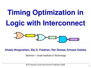
Timing Optimization in Logic with Interconnect. Arkadiy Morgenshtein, Eby G. Friedman, Ran Ginosar, Avinoam Kolodny. Technion – Israel Institute of Technology. SLIP (System Level Interconnect Prediction) 2008. Timing Optimization. A. B. Intro. Timing Optimization. function. A. B.

E N D
Timing Optimization in Logic with Interconnect Arkadiy Morgenshtein, Eby G. Friedman, Ran Ginosar, Avinoam Kolodny Technion – Israel Institute of Technology SLIP (System Level Interconnect Prediction) 2008
Timing Optimization A B Intro Timing Optimization function A B Special cases A Typically, a mixture of both B only gates only wires
Logic with Wires Intro Common Example 1 1 2 2 4 3 3 4 5 UART design 5
Intro The Interconnect Wall Logic w/o wires Long wires Interconnect Optimization Logic Gate Sizing Logical Effort Repeater Insertion
A B Intro Timing Optimization in Logic with Interconnect Logic w/o wires Long wires
Delay = Delay = Delay = Delay Optimal sizing Delayi = Delayi+1 gihi=gi+1hi+1 Intro Logical Effort (only logic) Delay model - delay of minimal inverter R0·C0 , technology constant - logical effort, gate type factor: e.g. ginv=1 - electrical effort, load driving capability - parasitic effort, due to output capacitance I. Sutherland, B. Sproull, and D. Harris, “Logical Effort - Designing Fast CMOS Circuits,” Morgan Kaufmann, 1999.
Delay = Delay = Delay = Delay Intro Limitations of Logical Effort Delay = Delay = Delay = Delay • No wires • No fixed side branches Logic with wires and branches LE breaks down ? ? ?
Intro Repeater Insertion (only wires) Delay ~ Length2 D = RC = 25 Delay ~ Length D = Σrc = 5 Optimal sizing Optimal number of repeaters - wire resistance - effective resistance of minimal inverter - wire capacitance - gate capacitance of minimal inverter H.B. Bakoglu, “Circuits, Interconnections and Packaging for VLSI,” Adison-Wesley, pp. 194‑219, 1990
= x Intro Properties of Repeater Insertion Assumptions of basic repeater insertion (RI) Equal size Equal spacing Terminal gates are similar to repeaters equal fixed Characteristics of RI Number and size of repeaters are independent Single optimal size for a given process and metal layer
Intro We Are Breaking The Wall Logic w/o wires Long wires Logical Effort Repeaters Insertion WANTED – solution for the mixed case Challenges: Gate placements Gate sizes Number of gates, repeaters
Our Approach to Timing Optimization Logic Gates as Repeaters (LGR) Gate placement (along the wire) Unified Logical Effort (ULE) Gate sizes Gate-terminated Sized Repeater Insertion (GSRI) Number of repeaters
Logic Gates as Repeaters - LGR “Where should the gates be located (along the wire)?”
Problem – delay reduction in logic with wire LGR The Idea • A solution – wire segmenting by repeaters • Drawback – power, area w/o logical functionality = waste • Proposed – logic gates as repeaters LGR - distribution of logic gates over interconnect - driving the partitioned wire without adding repeaters K. Venkat, “Generalized Delay Optimization of Resistive Interconnections through an Extension of Logical Effort,” ISCAS 1993
LGR LGR Delay Modeling Total Delay M. Moreinis, A. Morgenshtein, I. Wagner, and A. Kolodny, “Logic Gates as Repeaters (LGR) for Area-Efficient Timing Optimization,” IEEE TVLSI, 2006
LGR Optimal Wire Segmenting • Output resistance of driving gate i below average wire length i is increased • Input capacitance of successor gatei+1 above average wire length i is decreased • All gates are equal equal partitioning • In the case of a negative segment length, neighbor gates are merged
LGR LGR Results Critical path of 8-256 decoder circuit • Delay reduction of up-to 27% - by “moving” the gates • Further delay reduction – by scaling and LGR+RI M. Moreinis, et al., “Repeater Insertion combined with LGR Methodology for on-Chip Interconnect Timing Optimization,” ICECS, 2004.
LGR Optimal Gate Scaling • Enlargement of all gates by a uniform factor S to minimize timing • can be performed iteratively with Segmenting equal segments inverters
LGR LGR Segmenting and Scaling Uniform scaling performed for all gates • For intermediate wires LGR outperforms RI by up-to 55% • For long wires RI is faster • BUT: it requires 44 repeaters • Best for long wires – combined LGR and RI M. Moreinis, et al., “Repeater Insertion combined with LGR Methodology for on-Chip Interconnect Timing Optimization,” ICECS, 2004.
LGR Summary LGR • Logic gates serve as repeaters • No need for logically redundant repeaters • Delay reduction + lower area/power • Can be combined with RI
Unified Logical Effort - ULE “What is the optimal size of the gates?”
Capacitive interconnect effort Resistive interconnect effort ULE Unified Delay Model(including wires)
ULE Minimal Delay Condition Minimal Delay Equal Stage Delays
ULE Minimal Delay for Capacitive Wires General RC interconnect Capacitive interconnect (short wires and branches)
ULE ULE Convergence to LE and RI logic without wires repeater insertion special cases • repeater scaling • Logical Effort
ULE Some Algebra…
ULE Intuition of ULE Optimum = optimal size Delay caused by gate capacitance should be equal to delay caused by gate resistance
ULE ULE Optimality Size too small high resistance Size too big high capacitance
ULE Optimal Gate Capacitance • Expression for size of a single gate • Gate sizes along a logic path are iteratively determined
) 0 C × ( x opt e c n a t i m c µ a m L = 1 mm 100 m p m μ a 5 . 10 0 C m L = 0 µ 50 LE ULE Examples (1): ULE Sizing 100 • Equal wires • Total electrical effort H = 10 • L = 0 Size converges to LE • Longer wires ULE is faster • Long wires Fixed sizing xopt 90 80 70 60 50 40 30 20 10 1 2 3 4 5 6 7 8 9 Gate #
x opt L = 1 mm 0 . 5 mm 100 µm ) 0 C × 50 µm ( e c n a t i c a p a 10 µm C LE L = 0 Gate # ULE Examples (2): ULE Sizing 60 • Total electrical effort H = 1 • L = 0 Converges to LE (no scaling) • All wire lengths ULE is faster • Long wires Fixed sizing xopt 55 50 45 40 35 30 25 20 15 10 1 2 3 4 5 6 7 8 9
ULE So, What is Xopt? For long wires
ULE Optimum Condition for Long Wires For long wires
ULE Xopt and Repeaters Optimal sizing condition for repeater equal wires INV (g=1) H.B. Bakoglu, “Circuits, Interconnections and Packaging for VLSI,” Adison-Wesley, pp. 194‑219, 1990
ULE Solving Design Problems with Xopt • Layout constraint -optimal size of the repeater located between two wires
ULE Solving Design Problems with Xopt • Cell size constraint -optimal wire length with a repeater of size xrep
ULE Typical Design Example • Optimal ULE sizing • similar gates, similar wires • different gates, similar wires • similar gates, different wires • Gates with higher logical effort get bigger size • No fixed xopt in circuits with various gates and wires
ULE ULE Results Simulation Setup Critical path in a logic circuit (e.g. Adder) • Compared to Cadence Virtuoso® Analog Optimizer (using numerical algorithms) • 65 nm CMOS
Delay Optimization Logical Effort: higher delay ULE: minimal delay Analog Optimizer: minimal delay (but sloooooow) ULE • LE becomes inaccurate as the wire lengths grows • ULE is close to Analog Optimizer tool • within 9%
Run Time Comparison ULE Run time [min] • ULE run time is orders of magnitude shorter than the run time of Analog Optimizer • ULE run time is shorter than 1 second
Power-Delay Optimization in ULE ULE Power is function of gate and wire capacitances Optimal gate size Ci
Sizing for minimal P×D ULE Random logic path assumed with 10 stages x6 x8 x1 x3 x4 X5 x7 x9 X10 x2 L6 L8 L1 L3 L4 L5 L7 L9 L2 Four wire length scenarios S1: all wires L = 100µm S2: all wires L = 80µm S3: all wires L = 400µm S4: L = {900,600,150,300,800,200,400,150,250} (S4) Gate size (×C0) minimal Delay • Power-Delay optimization reduces gate sizes as compared to Delay optimization minimal Power×Delay
Reduced Energy, Low Delay Penalty ULE Delay Energy 4000 10 9 3500 minimal Power-Delay minimal Power-Delay 8 minimal Delay 3000 minimal Delay 7 2500 6 delay [ps] energy [pJ] 5 delay (ps) 2000 energy (pJ) 4 1500 3 1000 2 500 1 0 0 S1 S2 S3 S4 S1 S2 S3 S4 scenario scenario
ULE for Branches and Fanout ULE General ULE condition for gate sizing
Sizing in Path with Branches Gate Sizing with Branches 140 S1 120 S2 S3 100 S4 no branches 80 size 60 40 20 0 1 2 3 4 5 6 7 8 9 10 gate # ULE Four branch scenarios S1: Lb = 400µm, Cb = 1 for all branches S2: Lb = 400µm, Cb = 30 for all branches S3: Lb = {400, 100, 400, 400}µm, Cb = {30,1,30,1} S4: Lb = {100, 100, 100, 400}µm, Cb = {1,1,1,30} Lw = 100µm for all wires at critical path • Branches cause a change in sizing as compared to ULE without branches
Delay Optimization with Branches ULE • Additional delay reductionis obtained using extended ULE condition with branches
Unified Logical Effort Summary ULE = • Useful over entire range of problems • logic only – logic & wires – wires only • Computes optimal gate sizes • Low computational complexity
ULE One More Question: “When can I reduce delay by adding an inverter?”
ULE Adding an Inverter to Reduce Delay condition for inverter insertion