Download
1 / 101
1.01k likes | 1.03k Vues
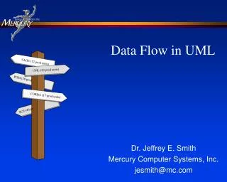
Yes, You Can Create An Architectural Data Model In UML The Handbook. DAMA Midwest Chapters October, 2012 David C. Hay. Essential Strategies, Inc. 13 Hilshire Grove Lane, Houston, TX 77055 ( 713) 464-8316 dch @essentialstrategies.com www.essentialstrategies.com. Today’s theme.

E N D
Yes, You Can Create An Architectural Data Model In UMLThe Handbook DAMA Midwest Chapters October, 2012 David C. Hay Essential Strategies, Inc. 13 Hilshire Grove Lane, Houston, TX 77055(713) 464-8316 dch@essentialstrategies.comwww.essentialstrategies.com
Today’s theme . . . A man may be a topologist or an acoustician or a coleopterist. He will be filled with the jargon of his field, and will know all its literature and all its ramifications. . . . . .but, more frequently than not, he will regard the next subject as something belonging to his colleague three doors down the corridor, and will consider any interest in it on his own part as an unwarrantable breach of privacy. These specialized fields are continually growing and invading new territory. The result is like what occurred when the Oregon country was being invaded simultaneously by the United States settlers, the British, the Mexicans, and the Russians—an inextricable tangle of exploration, nomenclature, and laws. Norbert Wiener, Cybernetics; 1948.1 1 Norbert Wiener. 1948, 1961. Cybernetics: of Control and Communication in the Animal and the Machine, second edition. (Cambridge, MA, The MIT Press). 2.
For example, data modeling and UML An inextricable tangle of…nomenclature… • Data Modelers • UML Modelers
An inextricable tangle of…nomenclature… For that matter,within data modeling . . . • Database Designers • Conceptual Data Modelers 4
Some history . . . Pre 1960 Fortran / COBOL 1967 Simula 67 1970 Structured Design 1980 The Personal Computer 1980 Small Talk / C++ 1988 Object-oriented Analysis 1991 Object Modeling 1992 Use Cases 1995 Java 1995 Design Patterns 1997 UML Pre 1960 Card decks, magnetic tape Mid 1960s 1st DBMS 1970 Ted Codd - Relational theory 1976 Peter Chen – Data models 1978 Data flow diagrams 1978 Relational Databases 1981 Information Engineering, Barker/Ellis 1987 Zachman Framework 1990s Data Management 1990s Business Rules 1995 Data Model Patterns
Today.we only care about these. About the Unified Modeling Language (UML) • Created in 1997, UML is an array of notations for modeling • Classes, • Activities, • State Machines • Use Cases • Interactions • It is intended to support object-oriented program design. • Note that by the late 1990s, outside the object-oriented community, modeling to support requirements analysis was alreadywell established : • Entity/relationship models (classes) • Data flow diagrams (activities) • State/transition diagrams (state machines) • Entity life histories (entity type behavior)
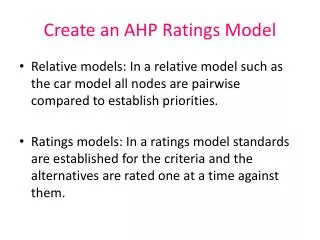
About Data Modeling . . . As stated, There are two groups of data modelers: Group one creates logical data models to support database design. Group two creates architectural data models to represent the structure of the business, independent of database technology.
Group one(DB designers) finds UML annoying because . . . The orientation is different: Database administrators: data as an asset, to be protected UML (OO) Designers: data as a support to programs. Relational structures deal badly with inheritance (and OO people have “attitudes”…).
Group two(business modelers) find UML annoying because . . . UML is not constrainedin defining what is a “class”. UML (as practiced) has a very peculiarway of naming relationships. UML notation and practices are not conducive to presenting models to the business. element ownership 0..* Classifier Field 1..1
Does UML supersede data modeling? Some would say no… Since it is about object oriented design… … it is not suitable for business analysis. So . . .
HERE Problem: UML is. . . • Despite its flaws, The Unified Modeling Language has been recognized as a standard in many quarters. • Clients and hiring managers keep asking if you have experience with UML. !!! How should we entity/relationship dudes deal with this?
It’s easy . . . Just build your entity / relationship models in UML! So I did . . .
So, I wrote another book in response . . . Which meant that . . . • My data modeling colleagues were convinced that I had completely sold out and gone over to the dark side . . . • . . . and my UML/object modeling colleagues accused me of bastardizing their sacred notation.
A companion volume . . . • Two audiences: • Data modelers convinced that UML has nothing to do with them. • UML modelers who don’t realize that architectural data modeling really is different … • … and the differences are important. • This is a handbook on how to use the UML class notation to produce an Architectural Entity / Relationship diagram.
Today’s Program Objectives Kinds of Models (and what we call them) Introduction to UML Notations About Classes About Relationships Unique Identifiers Unnecessary in UML Aesthetics and Presentation
Today’s Program Objectives Kinds of Models (and what we call them) Introduction to UML Notations About Classes About Relationships Unique Identifiers Unnecessary in UML Aesthetics and Presentation
Ok, let’s be honest . . . Data modelers themselves are sometimes a bit free-wheeling about what constitutes a class. Data modelers are often not as disciplined in making business structures presentable as they might be. Data modelers can be very casual in naming relationships 17/72
Present the characteristics of a high quality architectural data model… …no matter what notation is used. Not so Hidden agenda: 18/72
Specifically, This Presentation . . . Will show thebusiness-oriented modelers how to accomplish their objectives in UML. Will show the database designers how to do business-oriented modeling in UML. Will show UML object modelers how to bring business-oriented modeling into UML. (UML as a database design notation is for another presentation.) 19/72
After the book was published, I learned that . . . • My version of UML is something the OMG calls a “domain specific language” for entity/relationship modeling. • It even gets an acronym: “DSL”. • I knew I was tinkering with the language, • …but I didn’t realize it was something!
Today’s Program Objectives Kinds of Models (and what we call them) Introduction to UML Notations About Classes About Relationships Unique Identifiers Unnecessary in UML Aesthetics and Presentation
After all, itismy presentation… Please hear me out… Kinds of data models . . . • We modeling types are quick to criticize our clients for getting their vocabularies confused. • But what about us? What do we mean by . . . • “Conceptual” data model? • “Logical” data model? • “Physical” data model? • “Semantic” data model? • And now you’re adding “Architectural” data model? • For purpose of this presentation, here are the definitions:
Kinds of Models . . . Corporate Overview: Context for executive management, strategies. (Planner’s View) (Not “Conceptual”) Conceptual: Business-oriented, but in detail; technologically neutral. Two flavors: Semantic: In language of business owner; divergent. (Business Owner’s View) Architectural: Abstract, encompassing multiple groups: convergent(Architect’s View) (Not “Logical”) Logical: In terms of data management technology. (Designer’s View) (Not “Physical”) Physical: In terms of physical storage devices— table spaces, partitions, etc. (Builder’s View)
Context: ANSI’s Three ways to look at data (1975) . . . External Schema 3 Logical Schema(Relnl.) Internal Schema Conceptual Schema Internal Schema Logical Schema(XML) External Schema 2 External Schema . . . Four Physical Schema Physical Schema
Data(What) Activities(How) People(Who) Timing(When) Motiva-tion (Why) Network(Where) List of Important Things Organi- zational Units Business Events, Cycles Objectives/ Scope List of Processes Business Locations Business Vision and Mission Business Process Model Operationsby Business Location Org. Chart, Roles Master Business Schedule Business Policies and Rules Business Owner’s View Terms, Definitions Entity/ Relationship Diagram Data Links, Processing Locations State/ transactions, ELH Roles+Data (Use Cases) Essential Functions Business Rule Model Architect’s View Network Architecture (h/w, s/w types) User Interface, Security “Control Flow” diagrams Designer’s View Tables, Classes System Design Rule Design Data, physical storage design Detailed Program Design Screens, Security Design Network Construction Timing Definitions • Rule Specification Builder’s View Functioning System Working System The Architecture Framework . . .
The Architecture Framework . . . Data(What) Activities(How) People(Who) Timing(When) Motiva-tion (Why) Network(Where) List of Important Things Business Events, Cycles List of Processes Business Locations Organizational Units Business Vision and Mission Executive’s View Operationsby Business Location Master Business Schedule Business Owner’s View Business Processes Org. Chart, Roles Business Policies and Rules Terms, Definitions Data Links, Processing Locations State/ transactions, ELH Entity types, Relationships Roles+Data (Use Cases) Essential Functions Business Rule Definitions Architect’s View Network Architecture (h/w, s/w types) Tables, OO ClassesXML tags System Design User Interface, Security “Control Flow” diagrams Designer’s View Rule Design Detailed Program Design Screens, Security Design Physical Storage, Programs Network Construction Timing Definitions • Rule Implementations Builder’s View Functioning System Working System
Logical Model (Row 4) Architectural Model (Row 3) External Schema 1 Conceptual Schema External Schema 2 External Schema 3 Physical Model(Row 5) Semantic Model(Row 2) In terms of the Architecture Framework . . . Logical Schema(Relnl.) Logical Schema(XML) Physical Schema Physical Schema
Architectural Entity/Relationship Model “Conceptual” Data Model Database Design Model Object-oriented Design Model (UML) RELATIONAL DATA BASES Object-oriented Classes XML Schemas Business Owners’ Views (Semantics) Semantic Data Model, (E/R, SBVR, OWL) Terms, concepts.definitions Architect’s View(Integration of Business Owners’ Views) Entity types, attributes, relationships Architectural Data Model Tables, columns, keys Designer’s View(Technology) Classes, attributes, associations Tags
Today’s Program Objectives Kinds of Models (and what we call them) Introduction to UML Notations About Classes About Relationships Unique Identifiers Unnecessary in UML Aesthetics and Presentation
UML was originally designed to support object-oriented design… …not architectural business modeling. But do I have a deal for you . . .
We can use UML for a data model? • Yes…but with restrictions: • Restrict the definition of entity type. • Use a subset of the notation. • Recognize thatE/R relationships are not the same as OO associations. • Pay attention to Layout aesthetics. • Add unique identifiers.
Today’s Program Objectives Kinds of Models (and what we call them) Introduction to UML Notations About Classes About Relationships Unique Identifiers Unnecessary in UML Aesthetics and Presentation
Kinds of Notations . . . • Of interest to us . . . • Information Engineering – Most commonly used among data modelers. • Barker / Ellis –Most technologically independent • UML –The subject of today’s talk • Not of interest to us . . . • IDEF1X – Buried in relational design • Object Role Modeling – Different approach • OWL – Future presentations
Maximum Cardinality Attribute Minimum Cardinality Role Name Identifiers entity type Relationship Line Item_1 Order_1 Line Number Order Number part of Order Number (FK) Order Date composed of Quantity Price (Extended Value) Delivery Date E/R Notation (Information Engineering) . . .
E/R Notation (Information Engineering) . . . • Shows cardinality as graphics. Observer sees it. • Shows identifyingattributes and relationships. • Identifying attributesin separate section of entity type box. • Identifying relationship through combination of symbols:. • NOTE: Each relationship direction is structural, representing anassertion about the nature of the domain. • Minimalreferencesto technology… • … but there is a relational design bias: • Foreign keys implementing relationships • Complexity of identifying relationships.
Maximum Cardinality Attributes Minimum Cardinality Role Names entity type Relationship Identifiers E/R Notation (Barker-Ellis) . . .
E/R Notation (Barker-Ellis) • Shows cardinality as graphics. Observer sees it. • Shows identifying attributes and relationships with simple symbol. • NOTE: Each relationship direction is structural, representing anassertion about the nature of the domin. • No references to database or any technology.
Maximum Cardinality Attributes Minimum Cardinality Role Names Class Relationship(Association) UML Notation . . . ..1 Identifiers (None)
UML Notation . . . • Systematic cardinality notation (attributes and associations). • Cardinality textual, notgraphic. Viewer must read and understandit. • MAJOR ISSUE: In UML, an association is anavigation path, not a structure. • Identifier notation added in version 2.2. (Can also be added via “stereotypes”.) • No database connection . Full notation has object-oriented design symbols • …that we can ignore.
But it is the best practices, not the notation that is most important. About Notations . . . • Different notations (as implemented via different tools) make it easier or more difficult to do certain things. • The important dimension is good practices. • Best to support the practices here is Barker / Ellis • Second best is the revised version of UML. • Information Engineering’s bias toward relational database design is hard to thwart.
Today’s Program Objectives Kinds of Models (and what we call them) Introduction to UML Notations About Classes About Relationships Unique Identifiers Unnecessary in UML Aesthetics and Presentation
Note: No constraints as to what kindsof objects or classes were of interest. • Rumbaugh, J., Ivar Jacobson, Grady Booch. 1999. The Unified Modeling Language Reference Manual. p. 360. According to the “Three Amigos” . . . • An object is a “discrete entity with a well-defined boundary and identity that encapsulates state and behavior; an instance of a class” • A class, in turn, is “the descriptor for a set of objects that share the same attributes, operations, methods, relationships, and behavior.”1
According to James Martin and James Odell, “anything isanobject”.2 2. Martin, J., and James Odell. 1995. Object-Oriented Methods. (Englewood Cliffs, NJ: Prentice Hall). p. 34.
3. Barker, Richard. 1990. CASE*Method: Entity Relationship Modeling. (Wokingham, England: Addison-Wesley). An “Entity” on the other hand . . . • … is notjust any “discrete entity with a well-defined boundary and identity”. • … is limited to what Richard Barker calls things or objects “of significance, whether real or imagined, about which an organization needs information.”3 • An “entity type”, unlike other “classes”, is not concerned with operations, methods, or behavior. • Those belong to the world of “process modeling.” • An entity/relationship model is only concerned with the Structureof business data.
* * … or assertions in any other natural language, such as Polish, French, Chinese, or what have you. About language in the model . . . • An architectural entity/relationship diagram is essentially a graphic portrayal of English language assertions about an organization. • Therefore, the only language to appear on a diagram must be in terms relevant to the domain of interest. • Only business terms (and conventional English) may be used as the names of entity types, attributes, and the names of roles. • That is, no abbreviations, computer terms, or acronyms. • Words are not concatenated together. Spaces between words are shown (“Line Item”, not “lineItem”).
Entity Type names . . . • The name of an entity type is in the singular, and refers to an instance of that class. • Hence, Order and Line Itemare acceptable. • The name“Project history”is not. • An entity type called Project, on the other hand, could contain instances over time, so it may in fact be a project “history” • Database table names are not allowed, nor are abbreviations or acronyms. • Classes that are computer artifacts (“window”, “cursor”, and the like) are not allowed.
Again, because the model will be presented publically, spaces between words are required.
4 * 4, Barker, op. cit., p. 5-6. * This is something UML has over E/R notations. Naming Attributes . . . • In both E/R and UML an attribute is a characteristic of an entity type. • It “serves to qualify, identify, classify, quantify, or express the state of an entity” • In the previous example: • Order: “Order number” and “Order date”. • Line Item: “Line number”, “Quantity”, “Price”, “Delivery date”, and “/Extended value”. • “/” means a derived attribute. • /Extended value = Quantity * Price • Again, spaces are required (where appropriate). (“Delivery Date”, not “deliveryDate”)
Cardinality of attributes . . . • In UML, cardinality is represented the same way for attributes as for roles. • Minimum cardinality: • [1..1] – Mandatory:must be at least one value; may be no more than one value. Usually abbreviated “[1]”. • [0..1] – Optional: may or not have a value; may have no more than one value. • Maximum cardinalitymust always be ..1. Multi-valued attributes are not permitted.