Download
1 / 35
380 likes | 602 Vues
EKAS 2.19.31 Flexible cords and plugs to 1000 V. UEE31307 Certificate III in Refrigeration and Air Conditioning Stage 2A Units: UEENEEPOO3B Chris Hungerford Thursday, August 28, 2014. How is a flexible cord different from other cables?.

E N D
EKAS 2.19.31Flexible cords and plugs to 1000 V UEE31307 Certificate III in Refrigeration and Air Conditioning Stage 2A Units: UEENEEPOO3B Chris Hungerford Thursday, August 28, 2014
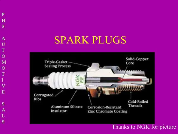
How is a flexible cord different from other cables? • The conductors in a flexible cord are made up of many more strands of finer wire than an ordinary cable (0.3mm). This allows the cord to flex without breaking the conductors. • The maximum cross-sectional area (CSA) of a conductor in a flexible cord is 4mm2. • Finally, the maximum number of insulated conductors (or cores) in a single cord is five. 2.19.31.A
Maximum length of flexible cords 2.19.31.A
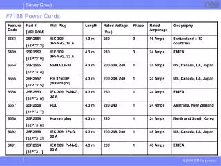
2.19.31.A Maximum current rating of flexible cords NOTES: 1 Where a flexible cord is wound on a drum, multiply current-carrying capacity by the appropriate factor, as follows: Number of layers: 1 2 3 4 Derating factor: 0.76 0.58 0.47 0.40 2 Flexible cords having tinsel conductors with a nominal cross-sectional area of 0.5 mm2 have a current carrying capacity of 0.5 A. 3 The current-carrying capacity is based on a cable maximum conductor operating temperature of 60°C in order to limit the surface temperatures for the expected use of such cables. Where flexible cords are used as fixed wiring, the current ratings are given in Tables 4 to 15 and 17. (Refer to Clause 3.3.2). 4 To determine the three-phase voltage drop, refer to the appropriate value in Table 46, Table 47 or Table 48. To determine the single-phase voltage drop, multiply the three-phase value by 1.155.
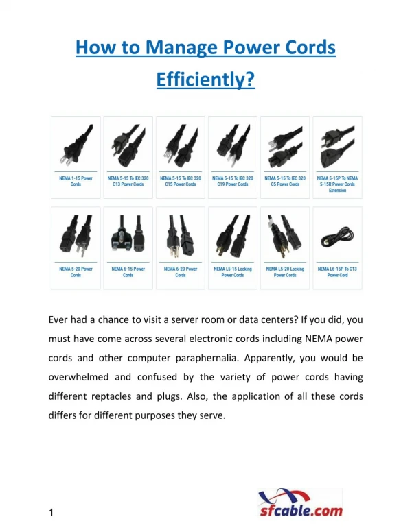
Electrical cables 3 Core & Earth Circular An electrical cable is identified by its: • Conductor material e.g. copper or aluminium • Conductor size e.g. 1.5mm² CSA • Insulation material e.g. rubber, glass, PVC • Number of cable cores e.g. 7/0.50 – i.e. 7 strands of 0.50mm circular diameter • Voltage grading e.g. 0.6 / 1 KV; 250V / 440V • Sheathing • Protection Conductor Strand 2.19.31.A Steel Wire Armoured SWA
Ratings of cables • Voltage rating, all cables have a maximum operating voltage. This is directly related to the type and thickness of the insulation material. • Temperature rating, table 3.2 AS 3000: 2007. • Cables are NOT rated in Current Carrying Capacity. A cable's current carrying capacity is determined buy how it is installed as per AS/NZS 3008.1.1 (Australian). 2.19.31.A
Selecting a cord or cable • Current carrying capacity of the cable. • Operating conditions; • temperature • voltage • installation factors such as in direct sunlight, mechanical protection, & thermal installation. • Number of conductors. 2.19.31.A
Plugs and sockets • There are many types of multiphase plug tops • 3 pin 2 phase & E • 4 pin 3 phase & E • 5 pin 3 phase neutral & E • Multi pin, 3 phase neutral & E + control keyways 35A 20A 15A 2.19.31.A
Electrical cables An electrical cable is identified by its: • Conductor material e.g. copper or aluminium • Conductor size e.g. 1.5mm² CSA • Insulation material e.g. rubber, glass, PVC • Number of cable cores e.g. 7/0.50 – i.e. 7 strands of 0.50mm circular diameter • Voltage grading e.g. 0.6 / 1 KV; 250V / 440V • Sheathing • Protection
TPS Thermoplastic Sheathed 3 Core & Earth Circular Twin & Earth Flat Sheathing Insulation Conductor Strand
2.19.31.A International Protection Numbers
AS/NZS-3000:2007 SAA Wiring Rules • 3.7.2.8 Flexible cords • Joints shall not be made in flexible cords. • Exceptions: Joint in flexible cords may be made - • Where used as installation wiring • By means of suitable cable couplers • Anyflexible cord shall be installed so that undue stress on its connections due to a pull on the cord is alleviated by a pillar, post, grip, tortuous path, orother effective means. • Knotting of the flexible cord shall not be acceptable for this purpose. 2.19.31.C
Accessories • All accessories must be suitable and as per Australian standards . • All accessories must be suitable for the application. • Wide variety of accessories can be accessed via suppliers catalogues. 2.19.31.C
A=Excellent B=Good C=Fair D=Poor 2.19.31.C
AS/NZS-3000:2007, SAA Wiring Rules 3.7 ELECTRICAL CONNECTIONS 3.7.1 General Connections between conductors and between conductors and otherelectrical equipment shall provide electrical continuity andadequatemechanical strength. • Solder less lugs • Crimps • Compression terminals • Soldered connections 2.19.31.C
AS/NZS-3000:2007 SAA Wiring Rules 3.7.2.2 Preparation for connection The insulation on a conductor shall not be removed any further than isnecessary to make the connection. For connections between insulatedconductors the connection shall be insulated to provide a degree ofinsulation not inferior to that of the conductors. Any damaged insulationshall be reinstated. 2.19.31.C
Yes Electrical insulation tape Epoxy kits Heat shrink No Masking tape packing tape sticky tape silicon mastic Insulation of conductors 2.19.31.C
Conductor colouringAS/NZS 3000 Table 3.4 Colour Function Earth/bonding Green/yellow Neutral Black Light blue Active Red, Brown, dark Blue, Orange, Purple, Grey, White, any colour other than green/yellow, green, black, yellow or light blue 2.19.31.C
Terminations and connections • Connections must not be soft soldered before compression terminations. • Must be seated correctly. • Free of dirt and oxides. • Use a suitable lug or connector. • Insulated to the equivalent of the original insulation. • Earth connection must be painted if exposed to weather 2.19.31.C
AS/NZS-3000:2007 SAA Wiring Rules 3.7.2.6 Mechanical stress All cables and conductors shall be installed so that there is no unduemechanical stress on any connection. 3.7.2.3.1 Loosening of connections Connections shall be made so that no loosening is likely because of vibration,alteration of materials or temperature variations towhich the connections are likely to be subjected in normal service. 2.19.31.C
The eight visual checks recommended are: • Check for obvious damage or defects. • Check that flexible cords are properly anchored • Check for any damage to flexible cords. • Check that maximum load warning labels are intact. • Check that any controls such as switches are in working order. • Check that covers and guards are properly secured as intended. • Check that any safety devices are in good working order. • Check that vents or exhausts are unobstructed. 2.19.31.D
Earth Continuity Test • Any Class I equipment with exposed metal parts must have its protective earth checked to ensure it is continuous from the earth pin of the plug to any exposed metal. The resistance must not be greater than 1Ω. Instrument Low reading ohmmeter. 2.19.31.D
Earth Continuity Earth Pin To Earth Socket 1 What is the value of earth continuity? Instrument Low reading ohmmeter. 2.19.31.D
Earth Continuity “Class 1” Instrument Low reading ohmmeter. Earth Pin to exposed Metal What is the value of earth continuity? 2.19.31.D
Insulation Resistance Test: • All equipment must be tested to ensure the integrity of the insulation, no electricity must be allowed to escape from the conductors or the appliance. Insulation resistance Tester Megohmmeter Scale multiplier Scale 2.19.31.D
Insulation Resistance “Class 1” Actives & Neutral To Earth Pin & Exposed Metal Megohmmeter Q What is the value of insulation resistance? 2.19.31.D
Insulation Resistance “Class 2” Q What is the value of insulation resistance? Megohmmeter Active & Neutral To Exposed Metal 2.19.31.D
Insulation Resistance “extension lead” Actives & Neutral To Earth Pin Megohmmeter 1M 1 Q What is the value of insulation resistance? 2.19.31.D
Polarity Active Pin To Active Socket low 1 What is the value of continuity? Instrument Low reading ohmmeter. 2.19.31.D
Polarity Neutral Pin To Neutral Socket 1M low 1 What is the value of continuity? 2.19.31.D Instrument Low reading ohmmeter.
What should the voltage be? What should the voltage be? V2=? V1 240v V2 415v V3 415v V2=? V1 240v V2 415v V3 240v V4 = 0V V3=? V3=? V1=? V4=? V1=? Is this correct? 240v 415v Is this correct? 240v 240V 240V 240v 240V 240V 240v 240v Reversed polarity L2 -N Reversed polarity L3-E 415v 2.19.31.D
Minimum records that should be completed and maintained A record of the inspection and test results. A record of faulty electrical equipment (has it been repaired or destroyed). 2.19.31.D
Energising supply • Only after the visual inspections and safety testing as per AS/NZS 3000:2007 has proven that the circuit is fit for purpose are you to energise the circuit. • Remove only your Danger tag. If another worker has their danger tag on the isolated point then you can not energise. • If clear: Energise the circuit. • Test for the correct and safe operation of the circuit, i.e. rotation, system performance, current draw, voltage, etc. • Prepare all your safety and performance documentation. 2.19.31.D