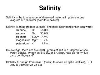
Control of Salinity in Lab Experiments with Arduino and Sensors
This guide focuses on controlling salinity levels in a lab setting using an Arduino and salinity sensors. The objective is to maintain salinity close to a specified setpoint, provided by the instructor, using DI water and a salty water solenoid valve. The process involves measuring the salinity through an analog voltage output, and adjusting solenoid valves based on readings. Techniques for calibration, control strategy adjustments, and management of systematic errors are also discussed, ensuring a stable experimental environment for accurate salt concentration monitoring.

Control of Salinity in Lab Experiments with Arduino and Sensors
E N D
Presentation Transcript
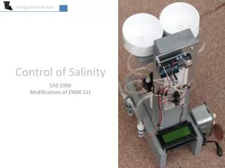
living with the lab Control of Salinity EAS 199B Modifications of ENGR 121
living with the lab salt water(1% NaCl) DI water General Idea • The objective is to keep the salinity close to a setpoint which will provided by your instructor • The salinity sensor measures the analog voltage output of the salinity circuit • Opening DI solenoid valve decreases salinity • Opening salty solenoid valve increases salinity 0.05 wt % NaCl ≤ setpoint for salinity ≥ 0.15 wt% NaCl(your instructor will provide a setpoint, such as 0.09 wt% NaCl)
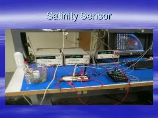
Power pin = 5V when HIGH(set high periodically to measure conductivity) living with the lab Review of Conductivity Sensor Wiring & Programming analog input pin(measures voltage across 10kΩ resistor) int power_pin = 4; // Digital I/O pin void setup() { Serial.begin(9600); pinMode(salinity_power_pin, OUTPUT); } void loop() { int input_pin = 2; // Analog input pin int salinity; // Reading from function salinity = salinity_reading( power_pin, input_pin); Serial.println(salinity); } 10 kΩ
Input power pin = 5V when HIGH(set high periodically to measure conductivity) living with the lab Review of Conductivity Sensor Wiring & Programming analog input pin(measures voltage across 10kΩ resistor) /* ---------------- salinity_reading ---------------- Return a single reading of the salinty sensor Input: power_pin = Digital I/O pin to supply power to the sensor input_pin = Analog input pin reads voltage across the fixed resistor */ int salinity_reading( int power_pin, int input_pin ) { int reading; digitalWrite( power_pin, HIGH ); // Turn on power delay(100); // Let sensor settle reading = analogRead( input_pin ); // Read voltage digitalWrite( power_pin, LOW ); // Turn off power return reading; } 10 kΩ
living with the lab Review of Conductivity Sensor Calibration • Collect analog output of salinity circuit, with output numbers ranging from 0 to 1023 (the Arduino has a 10-bit ADC) • Perform linear regression to determine the expected output of the conductivity circuit as a function of salinity • The Arduino environment can’t handle exponentials or logarithms, so try linear, polynomial and power fits polynomial linear power
living with the lab Examine Fits over Possible Salinity Range Do you see any potential problems? Which fit seems to be the best? Why?
living with the lab Equations Needed for Salinity Control Sketch output vs salt concentration use four or five digits for these fitting constants using algebra, invert this equation to obtain Salt concentration vs output use to compute setpoints for control use to salinity based on sensor output
living with the lab t1 > t2 since valve is left open an amount of time proportional to the error Control of Salinity valve = open salty water valve status valve = closed t2 valve = open DI water valve status valve = closed t1 system lag hysteresis 0.15 deadtimecompensation error upper control limit (UCL) salinity (%wt NaCl) 0.10 setpoint = 0.09 lower control limit (LCL) deadband 0.05 random variation of signal system upset by externally adding salty water system upset byexternally adding DI water 0.00 time
living with the lab Key Points • The valve is left open an amount of time that is proportional to the error. • small error = valve is open a short amount of time • large error = valve is open a long amount of time • The DI valve is left open longer than the salty valve when correcting for the same magnitude of error (DI=0%, setpoint = 0.09%, salty = 1%). • The system has memory . . . it takes time for the salinity of the water to become uniform (mixing, water in pump and tubing). The lag time is called hystersis. • Control is more stable if we wait for the system to stabilize after opening a valve. The deadtime compensation is set to allow the system to come to equilibrium before responding to error. • The upper and lower control limits are set so that random error will not cause the valves to open unnecessarily; these limits are often set three standard deviations of the error away from the setpoint. The difference between UCL and LCL is called the deadband.
living with the lab Control Strategy • The setpoint will be assigned by your instructor. Assume 0.09% NaCl here. • Compute the UCL, setpoint and LCL values for control of salinity. UCL and LCL depend on the size of the deadband. For demonstration purposes, assume that the UCL and LCL are 0.01%NaCl from the setpoint: • Control strategy: • if analogS > UCL (or 510) then open the DI valve an amount proportional to the error • If analogS < LCL (or 495), then open the salty valve an amount proportional to the error
living with the lab Setting UCL and LCL by Examining Random Error • A better way to determine UCL and LCL are by collecting analogS values for a salinity near the setpoint and then computing the standard deviation (s) of the “error” of analogS values. • Using this approach, 99.7% of random error will fall between the LCL and UCL, which means that your solenoid valve will be triggered due to a false alarm only 0.3% of the time. Example Readings to Illustrate Procedure
living with the lab Setting Deadtime Compensation • It takes time for your system to settle out after the salinity changes. • Assume the system whose response is depicted in the graph below is “upset” at 18 seconds due to a sudden addition of salty water. • At about 30 seconds, the salinity values stabilize (with continued random error at the new salinity level). • For this example, the deadtime compensation would be set to 12 seconds (30s - 18s). • This means that you would want to allow 12 seconds between salinity corrections. deadtime = 12 s time when salty water was added
living with the lab Strength of Response to Error • We will compute the amount of salty water that should be added to the current mixture to correct the salinity • Over correcting repeatedly causes the system to oscillate about the setpoint a correction that is too strong was applied 0.15 error upper control limit (UCL) salinity (%wt NaCl) 0.10 setpoint = 0.09 lower control limit (LCL) 0.05 overshoot (undesirable) a second correction is applied – this one is also too strong 0.00 time
living with the lab Apply a Response Proportional to Error • We will compute the amount of salty water that should be added to the current mixture to completely correct the salinity • We will open the solenoid valve long enough to remove a percentage of the error • For example, if the salinity is 0.152% and the setpoint is 0.09%, then applying an 80% correction will lower the salinity to 0.102%, which is computed as correction = (.00152-(.00152-.0009)*.8) • We call the proportionality constant the gain; gain is a common term used when working with industrial controllers 0.15 80% of error error upper control limit (UCL) salinity (%wt NaCl) 0.10 setpoint = 0.09 lower control limit (LCL) 0.05 0.00 time
living with the lab living with the lab • Class Problem • Assume that your fishtank system has a setpoint of 0.09% NaCl. Your instructor comes by your table and upsets your system by adding a good dose of DI water. The conductivity circuit returns an analog output that corresponds to a salinity of 0.04% NaCl (which is below LCL). • What is the target concentration if you have a gain of 0.80 (80%)? • Using this gain, how much salty water (1% NaCl) should be added? • How long should you leave the valve open if the flow rate is 0.2L/min? • Recommended assumptions: • The water leaves at the overflow is a mixture of water from the salty tank and the fishtank. • The most salty the overflow water can be is 1% NaCl, and the least salty it can be is 0.04% NaCl. Assume that 15% of the overflow water is 1% NaCl and that the rest is 0.04% NaCl. • Neglect density differences between incoming and outgoing water; that is, the mass of water that comes in from the salty tank is equal to the mass of water that leaves through the overflow.
living with the lab living with the lab Sketch Control Structure use your own data • Compute setpoint, UCL and LCL • Measure salinity to get analogS (the analog output of the conductivity circuit) • If analogS > UCL or < LCL & if time since last correction > deadtime then . . . • Compute the %wt NaCl • Compute the target salinity based on your gain • Compute the time that your salty or DI solenoid valves needs to be left open • Open the DI or salty valve for the computed time use your own data
living with the lab living with the lab To Do for Salinity Control: • Bring fishtank, water bottles, multimeter & computer to class next time • Determine flow rate through your solenoid valve (mass per unit time) • Recalibrate your system • Determine your fits • salinity as a function of analogS • analogS as a function of salinity • Collect data around 0.10% NaCl to determine the standard deviation of the conductivity output so that the UCL and LCL can be determined • Determine the deadtime compensation (system response time) • Write your control sketch