Download
1 / 28
280 likes | 394 Vues
Learn about optimization techniques for gas-lifted fields to maximize production and revenue while considering constraints and system performance. Topics include single and multi-well optimization, total system optimization, automation, and sustained gains. Discover how to achieve sustainable production gains through effective optimization strategies. Workshop details from ASME/API/ISO Fall 2003 Gas-Lift Workshop in Kuala Lumpur.

E N D
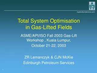
Total System Optimisationin Gas-Lifted Fields ASME/API/ISO Fall 2003 Gas-Lift Workshop , Kuala Lumpur, October 21-22, 2003 ZR Lemanczyk & CJN McKie Edinburgh Petroleum Services 1
Optimisation in Gas-Lifted Fields • Optimisation: maximisation of ‘benefit’ subject to constraints imposed by external conditions and the performance of the producing system • Reservoir • Wells • Pressure drops in pipes • Performance of surface equipment • Delivery pressures 2
Increasing THP Lift Gas Oil Production or $/day Export Gas +$ +$ Oil LiftGas -$ Water -$ Gas Injection Rate Single Well Optimisation Q P 3
Single Well Optimisation • Assumptions • Fixed tubing head pressure for all gas lift rates • Lift gas is available to the well at the rate and pressure required • Considered in the optimisation • Combined reservoir inflow and tubing outflow performance • Not considered in the optimisation • Effect of other equipment on the well and vice-versa • How lift gas is supplied to the well • Whether lift gas injected into this well wouldgive more benefit in another well 4
Multi-well Optimisation ProdManifold Flowline ProdManifold ProdManifold LiftGas ExportGas Oil Water +$ -$ +$ Flowlines Flowlines Flowlines LiftGas LiftGas LiftGas -$ -$ -$ 5
Multi-well Optimisation • Assumptions • Fixed separator pressure • Fixed total lift gas availability • Considered in the optimisation • Interactions between wells in production gathering network • Optimal allocation of limited supply of gas between wells • Not considered in the optimisation • How lift gas is supplied to the well • How changing operating conditions affecttotal amount of lift gas available 6
Total System Optimisation ProdManifold P ProdManifold ProdManifold Oil Water -$ +$ Lift GasManifold Export Gas +$ P Lift Gas P Q P P P P P Fuel Gas Q ExternalFuel Supply Q -$ 7
Gas Turbine Compression Stage 100% IncreasingSpeed Power Discharge Pressure Surge DecreasingEfficiency Stonewall Speed 100% Suction Flowrate Compressor Performance Fuel Gas 8
CHP IncreasingCHP Gas Injection Rate Ptub at operating valve Tubing Valve Gas Injection Rate Relationship between CHP and Qgi 9
WPS for GL Optimisation • Well Completion Details • Tubing • Gas-lift Valves • Open interval(s) • Reservoir completion • Reservoir Pressures • kh, Skin, PI • Production Tests • FBHP, FBHT Observations • Flowing Gradient Surveys Well PerformanceSurfaces Production System Geometry/Dimensions Well Active/Inactive Statuses Production Choke Sizes Current Flow Routing (Block Valve Statuses) Surface Eqpt Active/Inactive Statuses Current Pressures and Flowrates Economic Parameters OptimiserRecommendations 11
Solution Technique • A model is constructed containing all of the wells, the gathering & distribution networks and the surface equipment • The optimal solution to the model is found using Sequential Linear Programming (SLP) • Generic optimisation capability which can be applied to many different types of problems • Simultaneous simulation and optimisation • Proven ability to handle large, non hierarchicalnetworks with loops and branches andhundreds of wells 12
Automation & Optimisation • Off-line • Data input manually into system model • Results from system model implemented manually • Open loop • Data input automatically into model from SCADA • Results from model implemented manually • Closed loop • Data input automatically into model from SCADA • Results from model implemented automatically via set point controllers • Operator review may be required to ensure that implemented results are “sensible” 13
Closed Loop Optimisation Open Loop Optimisation Data Output Automatic Data Input Optimiser • OPERATOR • Advice • Approval • Implementation Data Output • OPERATOR • Advice • Approval • Implementation Setpoint Controllers Field 14
Offline Optimization Workflow Corporateeconomic parameters Current production equipment and network status • Process takes weeks • Highly skilled resource required Production Report performance curves Import updated well models into network models Update network model Run optimizationReview and output optimiser results Enter and validate production test data, re-tune well models Implement in field Archive well and network models used for optimization Update corporate information systems 15
Why Online? • Large Number of Wells • Complex optimisation problem • Reduce cycle time • Optimisation-to-implementation • Engineer’s time concentrated on value adding tasks • Goals • Automate Process • Automate Repetitive Tasks • Optimise 16
Sustained Gains Gains Simple Manual Optimisation Complex Manual Optimisation (Offline) Complex Automated Optimisation (i-DO) Sustainable Production Optimisation Optimisation gains revert to norm as system changes: automation of process is key to sustain the gains Increased Value Over ‘Do Nothing’ Time 17
Online Optimisation Historical Data Server Production Data Management Real-timeData ExpiredData Targets ProductionTests Conditions,Status SCADAHistorian Well PerfCurves Network Model and Optimizer WellModels OptimizedSet-points EconomicParameters SCADAServer Review,Approval Results LAN/WAN/Internet/Intranet CorporateDatabase EngineerPCs Web Client • Process takes minutes • Fully automated Process Data 18
Conclusions • Optimisation considering the total system can deliver additional production gains and costs savings over and above considering the production gathering network alone • The capability to perform total system optimisation in gas-lifted fields exists today. • A number of online gas lift optimisation systems have been installed and are operational today. 19
MARACAIBO CABIMAS 1.5 million BOPD 3.5 million BOPD Case Study: PDVSA - Venezuela • LakeMaracaibo, Venezuela • Large-scale implementation of gas lift • Pilot Area (Centro Lago) • Over 200 wells • 4 separation plants • 5 compressor trains • 10 liftgas manifolds 20
Case 1: PdVSA On-Line • SCADA data automatically loaded to give current block valve and compressor status and to constrain the optimisation to stay close to existing operating conditions • Price/cost and equipment constraint data loaded from Corporate databases • Gas injection well set-points sent directly to SCADA controllers (after production operator review as a block) • Recommended pressure control valve set-points and compressor operating conditions sent to production operators in open-loop advisory messages • Results stored in central database for access by other applications. 21
Optimal Separator Pressure • Separator pressure has to be high enough to transfer gas to compression plant • Total System Optimisation showed that it was possible to simultaneously reduce Psep and Qgi • 3% increase in oil production, 14% decrease in lift gas requirement From Wells SignificantPressureDrop Oil Water To Wells Export Gas Lift Gas 22
KOC POIS In 2000 KOC awarded a contract for Production Optimization and Information Systems to a consortium including EPS Objective - Deliver an integrated optimization and advisory system interfacing to the automation and SCADA systems covering four fields in North Kuwait Scope • Four fields in North Kuwait including 411 well strings • Of these 33 are water injectors, 91 gas-lifted producers, and 30 wells producing with ESP’s. • Complex network configuration allows wells to be switched between high, medium and low pressure separators as well as between wet and dry trains. 24
KOC POIS • Production Operation Information System (POIS) • EPS in partnership with Aspentech • On-Line Optimisation (inc. GL) implemented 2000-2002. • 253 NF + 91 GL + 34 ESP + 33 Injectors = ~400 wells • 5 Fields; 8 Producing Layers; 13 Fluid Models • 600,000 bopd • 217 SCADA – RTU Systems • Engineering support contract awarded 2003 despite intense competitive pressure 25
KOC POIS Abdali: 16 Wells to 2 GC via 13 6in lines 378 producers connected to 3 GCs through of 21 headers Ratqa: 20 Wells to 2 GC via 36in & 10in lines Sabriyah: 142 Wells to 1 GC thru’ 7 MF Raudhatain: 195 Wells to 3 GC thru’ 7 MF each Bahra: 5 Wells to 1 GC thru’ 7 MF 26
Lift gas to SA field Lift-Gas System 5x7 Possible inputs from RQ & AD fields 9 Sub-sheets holding 20-25 wells each 7x3 MF interconnecting all 194 wells across the field 7x3 MF outlets to production terminals KOC POIS Inside Raudhatain 27
Multi-header choice for lift-gas at present & for future Multi-MF choice for production at present and for future NP & GLwells (FG) KOC POIS Inside Raudhatain Subsheet RA-1 28