Download
1 / 13
130 likes | 357 Vues
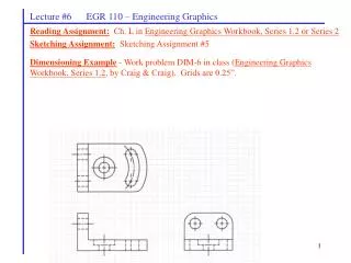
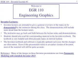
EGR 110 – Inventor Lecture #1. Welcome to EGR 110 Engineering Graphics. Inventor Lectures: Inventor lectures are intended to give a general overview of the topics to be demonstrated by the instructor during the class. The demonstrations will include more detail than the lectures notes.

E N D
EGR 110 – Inventor Lecture #1 Welcome to EGR 110 Engineering Graphics • Inventor Lectures: • Inventor lectures are intended to give a general overview of the topics to be demonstrated by the instructor during the class. The demonstrations will include more detail than the lectures notes. • The instructor may go back and forth between the lecture notes and demonstrations. • Students should also read the corresponding material in the Inventor textbook. The textbook is very helpful and often presents topics in tutorial fashion. • The Inventor textbook and software is typically updated each year, but the changes are often minor. Even if this presentation refers to an earlier version of Inventor, most of the material will still be quite accurate. • Reference: Many of the images in these Inventor presentations are from Parametric Modeling with Autodesk Inventor 2013.
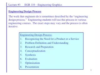
EGR 110 – Inventor Lecture #1 Feature-Based Parametric Modeling One of the key elements in the Autodesk Inventor solid modeling software is its use of the feature-based parametric modeling technique. The feature-based parametric modeling approach has elevated solid modeling technology to the level of a very powerful design tool. Parametric modeling offers many benefits: We begin with simple, conceptual models with minimal detail; this approach conforms to the design philosophy of “shape before size. Geometric constraints, dimensional constraints, and relational parametric equations can be used to capture design intent. The ability to update an entire system, including parts, assemblies and drawings after changing one parameter of complex designs. We can quickly explore and evaluate different design variations and alternatives to determine the best design. Existing design data can be reused to create new designs. Quick design turn-around.
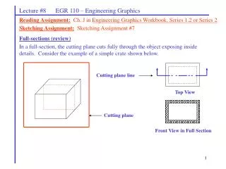
EGR 110 – Inventor Lecture #1 Application menu Quick Access toolbar Ribbon Tabs and Toolbars Browser Window Graphics Window Getting Started Launch Inventor and the initial screen below will appear. Select New to create a new file Select Standard (in).iptto create a new part. • File types in Inventor: • ipt (Inventor part) – will be begin the course by making single parts • idw(Inventor drawing) – parts and assemblies can be brought into drawing files where multiple views and additional features can be added • iam (Inventor assembly) – later we will combine several parts into a single assembly • ipn (Inventor presentation) – we might use this for exploded view drawings later Message or Single-line Help
EGR 110 – Inventor Lecture #1 Application menu Quick Access toolbar Ribbon Tabs and Toolbars Graphics Window Inventor 2013 Screen Layout Model Browser 3D Indicator Message or Single-line Help
EGR 110 – Inventor Lecture #1 2D sketches Many of our initial parts will begin with 2D sketches. These sketches will later be extruded (add thickness), revolved, or swept to create solid models. Select the one of the planes to create a 2D sketch in the plane. We may use the xy plane for our first few examples. Three plane choices are available (refer to the xyz icon below for orientation): xy plane – front view zx plane – top view yz plane – right side view xyz icon
EGR 110 – Inventor Lecture #1 As the name implies, a rough sketch is not precise at all. When sketching, we simply sketch the geometry so that it closely resembles the desired shape. Precise scale or lengths are not needed. Autodesk Inventor provides us with many tools to assist us in finalizing sketches. For example, geometric entities such as horizontal and vertical lines are set automatically. However, if the rough sketches are poor, it will require much more work to generate the desired parametric sketches. Here are some general guidelines for creating sketches in Autodesk Inventor: Create a sketch that is proportional to the desired shape. Concentrate on the shapes and forms of the design. Keep the sketches simple. Leave out small geometry features such as fillets, rounds and chamfers. Exaggerate the geometric features of the desired shape. Draw the geometry so that it does not overlap. The sketched geometric entities should form a closed region. Creating Rough Sketches
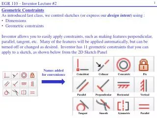
EGR 110 – Inventor Lecture #1 Creating Rough Sketches Dimensions and Constraints Once a rough sketch has been created, we control the sketch (and thus capture our design intent) by adding dimensions and constraints. Dimensions – used to control the length of lines, diameter of holes, angles, etc. Constraints – used to make various features horizontal, perpendicular, co-linear, tangent, etc. constraint tools dimension tools
EGR 110 – Inventor Lecture #1 Geometric Constraint Symbols
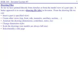
EGR 110 – Inventor Lecture #1 Sketch is extruded to make a solid Creating a Solid Feature - Extrusion 2D Sketches are often used to create solid features. Three key types of figures will be created using sketches: Extrusions (adding thickness or depth to a sketch) Revolutions Sweeps We will initially concentrate on extrusions.
EGR 110 – Inventor Lecture #1 Useful function keys F2 – Hold down F2 and the left mouse button to PAN F3 – Hold down F3 and the left mouse button to ZOOM in and out F6 – Automatically Zooms to Fit and rotates to an Isometric view Dynamic Viewing Inventor includes many useful tools for rotating, zooming, panning, etc. Useful mouse functions Zoom – Scroll center wheel on mouse to zoom in and out Pan – Hold down the center wheel on the mouse and move the mouse to pan the model or sketch
EGR 110 – Inventor Lecture #1 Browser Window Editing Sketch1 Editing Extrusion1 Browser Window The Browser Window (shown below) is an important part of Inventor that can be used to manage your design. It will show a series of features (extrusions, revolutions, holes, fillets, etc,) used to create the part. Some features, such as extrusions, are based on sketches. Any of these features or sketches can be edited at any time. The example below shows one extrusion (Extrusion1) that is based on Sketch1.
EGR 110 – Inventor Lecture #1 Orthographic vs Perspective We will typically use the default Orthographic (or isometric) style (where parallel lines always appear parallel), but Perspective style (where parallel lines appear to converge in the distance) is sometimes in artist’s renderings and in other cases. You might try it out. Visual Style We will typically use the default Shaded visual style, but you might try some of the others.
EGR 110 – Inventor Lecture #1 Printing For the first couple of assignments, we will print sketches and models directly (using File – Print). We may print the solid model (from an isometric view) and also print the related 2D sketches. This is not the preferred method of printing and may result in printouts that are not as clear as those we will create later by printing from a drawing file (idw). For now, do not worry about centerlines, arrow sizes on dimensions, notes, etc. These types of features can be easily added later in drawing files. An important point is that sketches are used to express features and constraints that are necessary to create the desired solid model. When we begin to use drawing files we will be able to produce professional looking drawings that following standard drawing conventions. In later assignments we will create professional looking drawing files from our models. In the first couple of assignments we will simply print the solid and the related sketches.