Silicon Rectifier and Zener Diode Characterization in Basic Electronics Laboratory
This laboratory experiment focuses on the analysis and characterization of silicon rectifiers and Zener diodes. Key objectives include examining forward I-V characteristics at room and elevated temperatures, understanding forward and reverse conduction, and evaluating diode parameters such as peak reverse voltage and surge current. Students will perform experiments on silicon diodes, utilizing measurement tools like DMMs and variations in temperature. Emphasis is placed on the temperature dependence of diode characteristics, ensuring a comprehensive understanding of semiconductor behavior under varying conditions.

Silicon Rectifier and Zener Diode Characterization in Basic Electronics Laboratory
E N D
Presentation Transcript
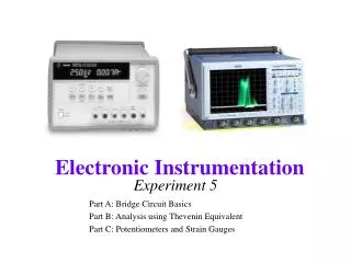
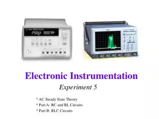
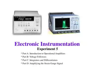
- + Experiment 5 EE 312 Basic Electronics Instrumentation Laboratory Wednesday, September 27, 2000
Objectives: • Si Rectifier Forward I-V Characteristics • Forward Conduction • at Room Temp (T) • at Elevated Temp (IVT Method) • Characteristics of Zener Diodes • Forward Conduction at Room Temp • Reverse Conduction at Room Temp
Semiconductor Diode Background: Two Types Vacuum Tube Diode
+ Anode I - Cathode One Way Semiconductor Diodes: Anode - Anode Cathode I + Cathode
670H16 Zener, Si metal case IN4742 Ge Glass case Anode + Cathode Types of diodes:
ID ID VD ID VD R External Limit VD 1/RD Diode Piece-wise approximation VT
Si Ge Tube Forward current (mA) Forward bias(V) Reverse bias (V) Reverse current (uA)
Parameters: • Maximum average forward current (IF,Max) • Full-cycle average current IF that the diode can safely conduct without becoming overheated • PRV, PIV,or VRM • peak reverse voltage • peak inverse voltage • voltage reverse, maximum (Maximum allowable reverse-bias voltage for the diode) PRV rating of 200 V means that the diode may breakdown & conduct & may even be destroyed, if the peak reverse voltage is greater than 200 V All mean the same
Surge or fault current (ISurge) • The amount of momentary overload current Isurge the diode can withstand without being destroyed • Temperature Range • Forward voltage drop (VF) • VF across the diode when it is conducting, given at the maximum average forward current • Maximum reverse current (IR,Max) • Maximum current IR the diode can handle for sustained period of time when operated as a Zener Diode • Other Parameters • Base diagram, total capacitance, reverse recovery time, recommended operating ranges
Forward Characteristics ID breakdown voltage I F,Max PRV VD VF Reverse Characteristics IR,Max ~ ~ IS
Forward Characteristics ID I F Rdyn=dV/dI Rd=VF/IF VD VF Reverse Characteristics
Procedures: 1- Silicon Rectifier (IVT) Forward I-V at 21 C Forward I-V at ~45 C & ~70 C 2- Silicon Zener Diode (I-V) Forward I-V at 21 C Reverse I-V at 21 C 3- PSPICE Simulation (Bell 242)
Components: • Silicon Rectifer (VBD < 200 V) • Si Diode (Zener, VBD ~ 27 V or ~ 12 V) • 0.1, 1.0, 4.7 kohms 2Watt Resistors • Heater Block & Tube Insulator • Temperature Probe • Variac (Shock Warning: Not Isolated From Power Line)
DMM I + DMM V 10._ V - ID VD 1- Forward Characteristics of Diodes R Vary R from 100 k to 100
R I + V 10.__V - Id [mA] Vd [V] 0.01 . . . 100 0.380 . . . 0.822 Vdc Rectifier & Zener R [ohm] Vdc [V] 10.38 . . . 10.822 100k . . . 100
2-Reverse Characteristics of Zener Diode(at voltages below breakdown) 4.7 k DMM I 1k + DMM 28V V 0-40V - ID VD
VOLTS DUAL TRACKING + 20V V - + 20V 0-20V 1A COMMON 0-20V 1A V - 40V + +5@1A 20V V - DC CONSTANT-VOLTAGE CURRENT-LIMITED FLOATING POWER SUPPLY + -
1 k DMM I + DMM V 0-40V - ID VD 2-Reverse Characteristics of Zener diode (at breakdown region)
1 k DMM I + DMM V 0-40V - Id [A] Vd [V] Zener 0.1 . . . 9.9m 0.001 . . . 29.0
3- Simulation (PSPICE) D1 2 0 Diode .Model Diode D(IS=1E-14 RS=5 N=1 BV=25 IBV=1E-10) default: Unit: IS Saturation current 1.0E-14 A RS Ohmic resistance 0 Ohm N Emission Coefficient 1 - BV Reverse breakdown voltage infinite V IBV Current at breakdown voltage 1.0E-3 A ISR, NR, IKF, NBV, IBVL, NBVL, TT, CJO, VJ, M FC, EG, XTI, TIKF, TBV1, TBV2, TRS1, TRS2, KF, AF
5- Temperature Characteristics of Ge Diode Thermocouple Probe “Hot Block” Ceramic Tube Heaters Ge Diode to Variac 5 cm
Temperature Probe switch Fluke Multimeter 200 mV range 1 mV/degree converter Box Probe
Temperature Dependence of IS See Sedra/Smith, TABLE 3-1, p. 156 Insert expression for the intrinsic carrier concentration ni2 into the expression for the the saturation current IS IS = C1 X T3 X exp(-EG/kT) where C1 is a constant The T3temperature dependence is weak compared to the exponential temperature dependence so that IS = C2 X exp(-EG/kT) where C2 = C1 X 3003 lnIS = ln(C1 X 3003 ) - EG/kT
Temperature Dependence of IS See Sedra/Smith, TABLE 3-1, p. 156 Insert expression for the intrinsic carrier concentration ni2 into the expression for the the saturation current IS IS = C1 X T3 X exp(-EG/kT) where C1 is a constant The T3temperature dependence is weak compared to the exponential temperature dependence so that IS = C2 X exp(-EG/kT) where C2 = C1 X 3003 lnIS = ln(C1 X 3003 ) - EG/kT
Precautions: • Always turn off the Variac and set its dial to zero when not using it. • At the start of the lab period, preheat the “hot block” to 40C. When you get to part 5, insert the diode into the block and allow a few minutes for the temperature to stabilize. • Do not exceed a temperature of 75C in the “hot block.” • Do not exceed the current rating for the diode: • Ge: IF, Max = 100 mA I R,Max = 1.0 mA • Si: I F,Max = 100 mA I R,Max = 100 mA
Must Submit Electronic Version Using Command submit ee312 E5ReportTuAM# Paper Version Also Required
Team Writing • Abstract & Report for Zener Diode reverse IV on the 1999 web • Introduction to be provided or omitted • One Partner does silicon rectifier IVT results & discussion for IS & n • Must provide results in a computer file to Partner in less than one week & submit to EE 312 Staff using submit command.
Other Partner uses information provided by partner to determine EG.Also include discussion and conclusions . Submit report electronically within one week of receiving partner’s contribution. Paper version also. • PSPICE Simulations Not Required. • Late penalties are -10 points per day and the day starts at 9:00 AM.