Download
1 / 24
240 likes | 397 Vues
NSTX-U. Supported by . Discussion of magnetic sensor upgrade plan for NSTX-U. S. A. Sabbagh , J.W. Berkery , J. Bialek, A . Diallo, S.P . Gerhardt, N. Logan, J-K Park, R. Raman, V. Soukhanovskii, et al. Coll of Wm & Mary Columbia U CompX General Atomics FIU INL

E N D
NSTX-U Supported by Discussion of magnetic sensor upgrade plan for NSTX-U S. A. Sabbagh, J.W. Berkery, J. Bialek, A. Diallo, S.P. Gerhardt, N. Logan, J-K Park, R. Raman, V. Soukhanovskii, et al. Coll of Wm & Mary Columbia U CompX General Atomics FIU INL Johns Hopkins U LANL LLNL Lodestar MIT Lehigh U Nova Photonics ORNL PPPL Princeton U Purdue U SNL Think Tank, Inc. UC Davis UC Irvine UCLA UCSD U Colorado U Illinois U Maryland U Rochester U Tennessee U Tulsa U Washington U Wisconsin X Science LLC Culham Sci Ctr York U Chubu U Fukui U Hiroshima U Hyogo U Kyoto U Kyushu U Kyushu Tokai U NIFS Niigata U U Tokyo JAEA Inst for Nucl Res, Kiev Ioffe Inst TRINITI Chonbuk Natl U NFRI KAIST POSTECH Seoul Natl U ASIPP CIEMAT FOM Inst DIFFER ENEA, Frascati CEA, Cadarache IPP, Jülich IPP, Garching ASCR, Czech Rep NSTX-U 5 Year Plan Meeting January 10th, 2013 PPPL V1.2
Meeting Purpose: Request to reach closure on planned / desired expanded magnetic sensor set for the 5 year plan • Comments / Questions from Jon • Sufficient detail on the expanded shunt tile set • Do we have more detailed info on B-probes in the divertor? • Where, how many, what orientation, etc? • Do RWMs make any SOLC that is worth detecting? • Budget for sensors ~ $0.5M (perhaps up to $1M) • Stefan’s brief suggestions from past email discussion to make best case for the sensors • measuring the magnetic signature of Hiro/Halo currents • measuring the MHD at the injector during CHI • measuring SOL current filaments and ELMs • Further details • schedule for divertor upgrades that might mandate sensor removal • optimal sensor polarities, effective areas, integrator/digitizer schemes Jon has requested 15 minute summary talk at tomorrow’s NSTX-U meeting
Upgraded magnetic sensor plan will support research in several areas (for discussion) • Global mode diagnosis • Measure theoretically expected mode alteration at high bN • RWM physics and control • Improve RWM state space active control and observer • Enhance input to disruption warning system • Disruption characterictics • Expanded shunt tile set for halo current diagnosis, etc. • Do questions remain re: specs for halo current meas. / shunt tile set? • Snowflake divertor and ELM characteristics • Additional requests / detail needed for probes to run snowflake? • Further extensions of magnetics for ELM research? • CHI • Additional flux loop positions requested – what about B probes?
2.0 133775 t = 0.655s mode 1 1.0 Z(m) q 0.0 -1.0 mode 3 mode 2 -2.0 0.0 1.0 2.0 R(m) Multi-mode computation shows 2ndeigenmode component has dominant amplitude at high bN in NSTX stabilizing structure dBn from wall, multi-mode response dBn RWM multi-mode composition • The two primary global modes have increased amplitude in the divertor region • This was also found theoretically for NSTX for single mode computations during the design of the present NSTX system bN = 6.1 mode 2 mode 3 dBn amplitude (arb) Unstable mode 1 Stabilized by rotation S. Sabbagh, et al., NF 2004 ideal eigenmode number mmVALEN code
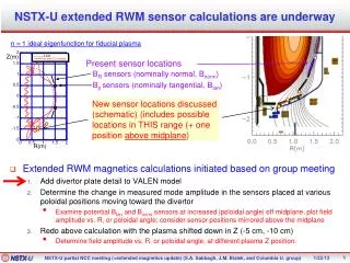
Theory indicates that positioning new sensors closer to divertor will improve mode measurement n = 1 ideal eigenfunctions for fiducial plasma Present sensor locations Bpsensors Z(m) BRsensors (schematic) new sensor locations • Mode amplitude increases as poloidal angle increases toward the divertor • Initial suggestions / priorities • Stay with 12 toroidal positions – same as present sensors • 1st: Bp sensors closer to the divertor region • 2nd: BR sensors in a nearby location to new Bp sensors that is not strongly coupled/shielded by passive plates • 3rd: Bpsensors at an additional poloidal location • 4th: BRsensors at an additional poloidal location R(m) ADD mode helicity plot here, with new sensors indicated showing how the phase changes significantly at different poloidal positions near divertor
SPG Idea #1: Mount them under Secondary Passive Plate Lip • Replace this tile with sensor box. • Would be partially shielded by SPP • Might need to retain part of the front of the tile, but much could likely be eliminated. • Wire extraction fairly simple. • Boxes may need to be curved to follow outline of plate.
SPG Idea #1: Mount them under Secondary Passive Plate Lip • Replace this tile with sensor box. • Would be partially shielded by SPP
SPG Idea #2: Mount them under outer divertor bull nose tiles • Place curved sensor box in this volume. • Is reasonably well shielded from plasma by improved bull-nose tiles. • Wire extraction likely to be difficult. • Would be partially electromagnetically shielded by divertor.
SPG Idea #3: Sensors in Tiles • Tiles are only about 0.9” thick, and have a T-bar right down the center. • Makes installation of a traditional BP (~BR) sensor difficult. • Could imagine a very thin “Hiro” sensor mounted above the T-bar. • Could fabricate a single larger tile, taking the area of 2-4 existing tiles. • Wrap a BN (~BZ) sensor around the tile edges. • Sort of like how the BR sensors are mounted to the PPPs • Would likely trap the t-bars • Are there thermal issues with larger tiles? • Need to check the effective area. Outline of larger tile.
From Roger: Flux loops and Magnetics sensors that would be beneficial for CHI research • Poloidal flux loops in these locations would benefit CHI Best if the same configuration is also adopted for the upper divertor
Magnetic diagnostic items from Masa’s section • The density of poloidal magnetic field probes flux loops in the divertor region will be increased • For improving the magnetic reconstruction of snowflake divertorconfigurations • Asecond vertical array of poloidal field sensors will be installed on the center column • Increasing the redundancy of these critical measurements • The density of poloidal magnetic flux loops in the vicinity of the divertor coil mandrels will be increased • Allowing better reconstruction of the eddy currents induced in these support structures
Stefan’s Comments/Questions re: extended RWM sensors (+ SAS replies) • Is it necessary that these be up/down symmetric? • Maybe focus on LSN discharges for the first installation? • SAS comment: Yes – also has advantage of higher m resolution (similar to comment by Jong-Kyu regarding higher n’s) • Is likely premature to consider the details: • Is lower divertor going to be modified for pumps or lithium systems? • All suggested locations would need changes if a cryopump is placed in the lower divertor. • However, cryopump would also allow for opportunities for sensor integration • How many years of operating with these sensors is required to make them worth the effort? • SAS: Even one year would provide key data, and results might argue to keep them in (e.g. for improved operation of RWM state-space controller) • Who will do this work? • SPG not likely to have time for the details.
Note: The following four slides are from Stefan from July 13th, 2012
Determine SOLC Distributions by Magnetic Probe Arrays and Tile (Halo) Current Sensor Arrays (with Stefan Gerhardt) • SOLC, acting as a transforming agent of external error field, could be a game changer in assessment of max tolerable error field in ITER.An unstated assumption, underlying a stringent symmetry requirement (5 x 10^-5) for ITER based on a device-size scaling law, is that a (small) applied error field directly caused observed adverse plasma response (rotation slow-down/stoppage followed by a disruption).An external error field, intrinsic or applied, may cause SOLC to flow, which in turn generates an error field of its own that is, not only greater in magnitude but also more destructive in nature, than the external field. A much more relaxed symmetry requirement could emerge, if adverse plasma response was a consequence of this transformed error field, provided SOLC can be controlled or eliminated. • Study and control of SOLC, as a source of dynamically-generated error field, will broadly impact NSTX-U research, as achieving low-collisionality regimes through eliminating rotation slow-down/stoppage, is central in demonstrating the relevance of NSTX-U program to future STs, ITER, and beyond. • Study roles played by SOLC in ELM physics. • Study post-disruption halo current (Gerhardt). Takahashi NSTX Brainstorm
Determine SOLC Distribution by Magnetic Probe Arrays and Tile (Halo) Current Sensor Arrays (with Stefan Gerhardt) – cont. • Determine a spatio-temporal structure of SOLC, which generates both axisymmetric and non-axisymmetric fields.Solve an inverse problem using an SVD method, i.e., calculating a SOLC distribution from a measured SOLC-generated field distribution. Tile current, measured only at discrete locations, will serve as constraints on the solutions. • Develop algorithm for taking advantage of tri-axial field measurements, which can define a field vector at the measurement point completely, both in magnitude and direction. Three field components should exhibit correlated features that are characteristic of the nature of the field source. • Use a toroidal magnetic sensor array on the center stack as a “pseudo-Rogowski coil” to measure post-disruption halo current (Gerhardt). • Transfer sensors, integrators, and digitizers from the structural error field measurement project. Takahashi NSTX Brainstorm
Notes from Steve and Stefan’s Emails on 11/27/2012 • Applications of such an upgraded sensor set include: • Resistive wall mode measurement closer to the divertor region, based on the theoretically expected large amplitude of high beta n = 1 single mode, and the n = 1 multi-mode there. • This upgrade would also factor in directly to the RWM state space controller. • Measuring the magnetic signature of Hiro/Halo currents. • Measuring the MHD at the injector during CHI. • Measuring SOL current filaments and ELMs. • Several considerations must be accounted for, however, including: • the optimal sensor polarities • effective areas • integrator/digitizer schemes • the schedule for divertor upgrades that might mandate removing those sensors
SAS notes from 5 Year Plan The theoretically computed increase in global eigenmode amplitude in the divertor region at high bN will be investigated utilizing an expanded RWM sensor set. The prominence of this mode in the full computed multi-mode spectrum and the impact on active mode control will be determined. The impact of snowflake divertor operation on this mode will be assessed. Dual-component active RWM control using proportional gain will be retained on NSTX-U. The system will be improved by adding additional RWM sensors closer to the divertor region. Physics design studies [[i]] and multi-mode analysis of NSTX (Section 2.2.1.2.2) theoretically show significantly increased mode amplitude in the divertor region at high bN. This characteristic will be studied using the upgraded sensors, which will be incorporated into the RWM feedback system to further improve mode detection. The significant mode amplitude in the divertor region, found both in single and multi-mode studies, motivates the installation of magnetic sensors closer to the divertor region to study the RWM eigenfunction, to compare to expectations of ideal theory, and to directly improve comparisons of the measured mode shape to the real-time RWM state-space controller model (see Section 2.2.1.3.1). The addition of the present radial field sensors, and the planned magnetic sensor upgrade will also provide additional physics research capabilities for NSTX-U, including the comparison of using radial field sensors alone versus dual-field components in feedback with the RWMSC vessel model included in the calculation. Such testing will be important to determine sensor and actuator needs for future devices, especially where additional shielding of sensors will be needed, such as in ITER. Second, the multi-mode spectrum of NSTX (Section 2.2.1.2.2) shows that a multi-mode RFA analysis should be used at sufficient bN. The new capabilities of NSTX-U will allow the application of applied field with different n numbers, and the additional information provided by the upgraded sensors with positions closer to the divertor may provide further mode discrimination. [[i]] S.A. Sabbagh, et al., Nucl. Fusion 44 (2004) 560.