Download
1 / 14
140 likes | 320 Vues
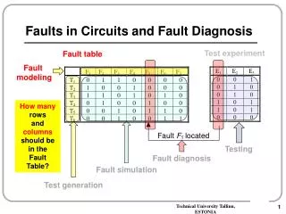
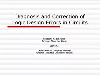
Diagnosis and Correction of Logic Errors in Circuits based on probability. Student: Yu-Lin Hsiao Advisor: Chun-Yao Wang 2006.3.08 Department of Computer Science National Tsing Hua University, Taiwan. Outline. Problem Description Diagnosis Preliminary idea Correction Future work.

E N D
Diagnosis and Correction of Logic Errors in Circuits based on probability Student: Yu-Lin Hsiao Advisor: Chun-Yao Wang 2006.3.08 Department of Computer Science National Tsing Hua University, Taiwan
Outline • Problem Description • Diagnosis • Preliminary idea • Correction • Future work
Problem Description • Given two netlists C_org and C_opt C_org is the original circuit C_opt is the timing/area optimal circuit • If at least one function among both circuits is not equivalent, the C_opt is consider as having design errors.
Problem Description (Cont’d) • Assume only one simple design error in the C_opt, and its error type is missing inverter or extra inverter. • The whole circuit only has AND, OR, NOT gates, and it has no redundant sub-circuit.
Diagnosis • When the probability of two functions are not equivalent, the diagnosis procedure is called. • Diagnosis procedure will trace back the circuit and find out a potential error location. • A potential error location may not be an actual error, diagnosis procedure is repeated until an actual error is found.
Search potential error location • It is very expensive to examine all lines until an error location is found. • We have to reduce our search space. Some impossible potential error locations can be pruned.
Search potential error location (Cont’d) Potential Error location a Potential Error location b An error location must exist within the intersection of the backtrace cones of all erroneous POs
Preliminary idea f = ab+c a 01010101 b 00110011 c 00001111 0001 00010001 1/3 = 0011 0111 a 00011111 0111 b 1/5 f c 00001111 1/17 0111 a: positive unate b: positive unate c: positive unate
Preliminary idea (Cont’d) f = ab+c a 01010101 b 00110011 c 00001111 a:negative unate 11101111 11100000 a 0111 b f c a: positive unate b: positive unate c: positive unate a: negative unate b: negative unate c: negative unate a: negative unate b: negative unate c: positive unate
Preliminary idea (Cont’d) • If a variable which only appears at most one cube in a function is either positive or negative phase , we can check its change of unate property to detect where an error is. • Extra or missing inverter in a circuit can inverse the unate property of relative variables.
Preliminary idea (Cont’d) f = ab + bc+ ac May locate wrong line!! a b 01001111 c 11110111 a: positive unate b: positive unate c: negative unate a: positive unate b: negative unate c: positive unate
Preliminary idea (Cont’d) • If a variable has both phases in cubes in a function , it can be positive unate, negative unate or binate. • In this case, extra or missing inverter in a circuit may not change the unate property of variables. • This idea can’t solve a circuit with signal correlation.
Correction • We define two types of error model, however we don’t have to check a circuit twice. If error occurs, we only need to add a new inverter If error occurs, add a new inverter means deleting the original inverter.
Future work • Based on unate property checking method, try to solve signal correlation problem.