Schedule for ILC 45 MV/m Input Coupler (disk type and capacitive coupling, Kazakov type)
60 likes | 242 Vues
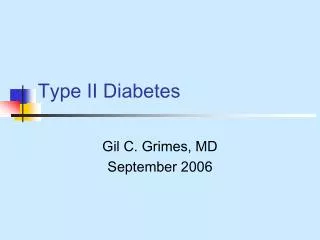
Schedule for ILC 45 MV/m Input Coupler (disk type and capacitive coupling, Kazakov type). 2005. 2005. 4. 5. 6. 7. 8. 9. 10. 11. 12. 1. 2. 3. 1) contract for ILC 45 MV/m. 7 months. rf power. 2) fix the electric parameters. 3) make mechanical design.

Schedule for ILC 45 MV/m Input Coupler (disk type and capacitive coupling, Kazakov type)
E N D
Presentation Transcript
Schedule for ILC 45 MV/m Input Coupler(disk type and capacitive coupling, Kazakov type) 2005 2005 4 5 6 7 8 9 10 11 12 1 2 3 1) contract for ILC 45 MV/m 7 months rf power 2) fix the electric parameters 3) make mechanical design 4) critical discussion with company for technical issues in details HA-997 5) order the ceramics (disk type) 3 months 6) R&D • brazing test • DLC test • isolator • waveguide using S-band TRW at KEKB to cavity mainly design work mainly design work
Possible Structures for Input Coupler Input coupler comprises of four modules: 1) antenna at cold side 2) rf window 3) coaxial line 4) coaxial transformer rf power coaxial transformer possible structures rf power coaxial line cylinder shape rf window rf window rf power antenna disk shape rf window
High Purity Alumina & Diamond-like Carbon Carting • Major characteristics of HA-997 (NTK) • - Alumina contents (%): 99.7 • - Specific gravity: 3.95 • Dielectric constant (): 9.8~9.9 (8-GHz) • Temperature coefficient of (ppm/ºC): +90~+110 • - Dielectric loss tangent (Tan ): 3x10⁻⁵ (8-GHz) Super hard diamond-like carbon coating using Gas Cluster Ion Beam Assisted Deposition (GCIB). Nomura Plating Co.,Ltd. GCIB CVD Hardness [GPa]: >50 20~30 Young’s modulus: 270 140 Component: Carbon Carbon+H2 Diamond content: Rich Weak Density: High Low Heat resistant: 500ºC <400ºC (at air) Flatness (Ra, nm): <0.5 0.5 Al2O3 99.7% Diamond-like carbon with 100-nm of coating thickness will provide good uniformity. NOTE: need investigate rf characteristics at high power. • Advantages • almost uniform grain size. • no large voids found between grain boundaries.
High Power Test Using TWR We used Traveling Wave Resonator (TWR) to conduct high power tests of rf window ceramic disks, which were made with varying fractions of sintering binder (MgO). ceramic disk t: 3.5-mm, Ø92-mm ceramic disk ceramic disk waveguide Cutaway view of rf window at S-band frequency.
Input Coupler for ILC 45 MV/m • Basic Technologies: • low electric field gradient at air side • < 1 kV/mm • - high purity ceramic >99.7% • - use new brazing material • Ag:Cu Au:Cu (:Ti, option) • surface coating TiN, and or • diamond-like carbon H. Matsumoto, S. Kazakov USE NEW RF FEED SYSTEM. - separate coupling adjustment from coupler adopted the jB generator. (system simple) - no tapering part at rf window to reduce multipactoring. (improve reliability) - try to omit an rf window for room temperature side. (reduce cost) Air? or Vacuum? 5-MW, 1-msec Klystron 0.9 kV/mm @ 5-MW (~1 kV/mm @ Air) 3dB HYBRID RF load EIA650 (8.255-cm x 16.51-cm) Isolator Z(L)=jZ0tan(2L/g) Vacuum or dray N2 jB generator Klystron Cavity W.G. Coupler not scaled Anchors using Invar 9-cell x 4 (45 MV/m) Disk type window * Electric field gradient in the waveguide (kV/mm) @ 5-MW L-band (8.255-cm x 16.51-cm): 0.9 -> seems not enough margin in air S-band (3.404-cm x 7.21-cm) : 2.2 -> no good in air, good in SF6 (but no good at 10-MW) g/4 impedance matching
Gas Pressure VS Breakdown Voltage Relative electric strength of various gases at atmospheric pressure. Air 1 N2 1 SF6 2.5 SF6(30%)+Air(70%) 2 C5F8 (Freon) 5.5 H2 0.5 Comparison of the vacuum and air for system configuration Items Vacuum Air Dielectric strength (kV/mm) : 7~19 (practical) ~1.0 (practical) (at S-band) 2.9 (ideal) Equipment: Ion pump, Gages Blower, Filters (dust, mist) Maintainability: Very simple No good (need change the filters frequently) Environment-friendability: Very good Good (but large amount of wasted parts, noisy blower sound) System reliability; Very good Good (but, consider: blower lifetime, vacuum leak at coupler, rf phase stability) From Paschen curve in figure, high gas pressure dose not great contribute to increase the breakdown voltage. The breakdown voltage in a vacuum is much higher than the other gases. So, we would like to consider the vacuum type waveguide system for a backup scheme.