Download
1 / 74
760 likes | 982 Vues
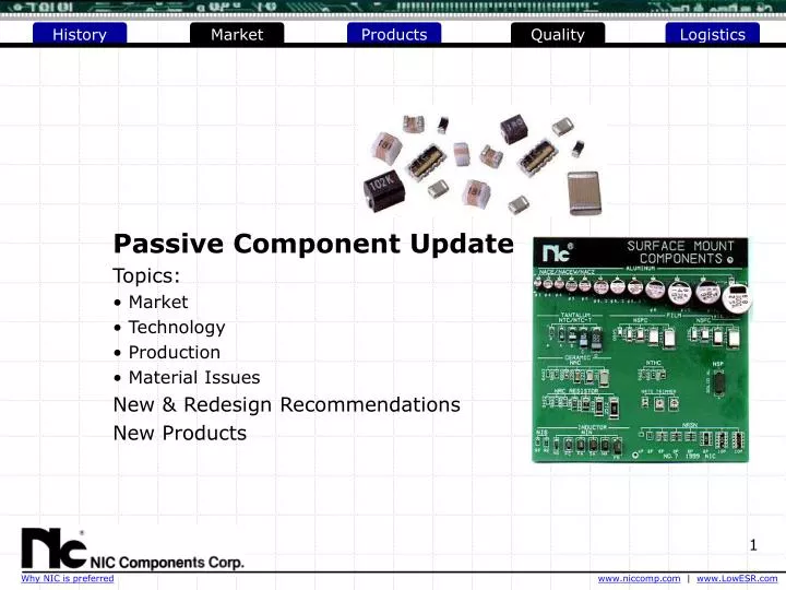
Passive Component Update Topics: Market Technology Production Material Issues New & Redesign Recommendations New Products. Sources: Nippon Industries Company Ltd (Japan) NIC Components Corp. (Taiwan) Paumanok Publications, Inc

E N D
Passive Component Update • Topics: • Market • Technology • Production • Material Issues • New & Redesign Recommendations • New Products
Sources: Nippon Industries Company Ltd (Japan) NIC Components Corp. (Taiwan) Paumanok Publications, Inc Leading passive component market analysts… & publishers of Passive Component Industry Magazine Bi-monthly look at the passive component market and technology www.paumanokgroup.com/ Reed Electronics Research www.rer.co.uk Electronic Buyer News (EBN) www.ebnonline.com Electronic Component News (ECN) www.ecnmag.com
Changing Technology Impact Passive Devices • Technology Innovations • Lower voltage of operation = increased circuit current = higher demands on voltage - power management circuitry = tighter line (supply voltage) regulation (reduce ripple voltage) = increased demand for low ESR capacitors • Faster circuit speeds = reduced response time for voltage - power management circuits = increased demand on capacitor bank • Higher frequency operation = reduced trace distances = better performing & smaller devices • All impact signal & supply voltage integrity
Development of Passive Components Passive component research & development: New & Improved Materials + improve characteristics + reduce costs Improved Processing & Equipment + expanded available range + increased production + reduced components sizes
Passive Components Markets • Review: • ~12% growth in 2002 Passive Component Market ($ value) as compared to 2001 level • Price erosion is substantial • Limited capacity expansion CAPACITOR MARKET (2002) 615 Billion units = $8.38 billion
MULTILAYER CERAMIC CHIP CAPACITORS : Materials Shift Electrodes(PdAgor BME- Base Metal: Nickel) 2002 Estimates:70% of global MLCC production is BME Nickel Electrode Powder Shipments 1995 = 95 Tons 2000 = 645 Tons 2005(E) = 1830 Tons BME Pd-Ag
MULTILAYER CERAMIC CHIP CAPACITORS : Materials Shift Pd-Ag … Price Per Troy Ounce (USD)
MULTILAYER CERAMIC CHIP CAPACITORS : Developments • Nickel electrodes & Copper terminations = reduced component costs • Greater equipment (firing) costs • Increased number of layers [ >100 layers ] • 1uF and above = very low ESR [ sub 0.010ohm @ 100KHz) • X7R (-55 ~ +125) & X5R (-55 ~ +85) = ±15% Cap change • Encroaching upon tantalum electrolytic range • 100uF / 6.3VDC [1210 in X5R & Y5V TCs] • Thinner (sub–micron) dielectric layers = lower voltage ratings • Voltage-coefficient effects • Aging effects & piezo-electric noise
MULTILAYER CERAMIC CHIP CAPACITORS NMC Series: MLCCs Ceramic Chip Capacitors 0201 sizeNPO = (101) 100pF / 25VDCX7R = (332) 3300pF/16VDCX5R = (103) 0.01uF/10VDCNew!X5R = (104) 0.1uF/4VDC0402 sizeNPO = (471) 470pF / 16VDCX7R = (104) 0.10uF/10VDCNew!X5R = (105) 1.0uF/10VDCY5V = (105) 1.0uF/6.3VDC0603 sizeNPO = (182) 1800pF / 50VDCNew!X7R = (105) 1.0uF/10VDCNew!X5R = (225) 2.2uF/6.3VDCY5V = (225) 2.2uF/10VDC 0805 sizeNPO = (682) 6800pF /50VDCNew! X7R = (475) 4.7uF/10VDCNew! X5R = (106) 10uF/6.3VDCY5V = (106) 10uF/10VDC 1206 sizeNPO = (103) 0.01uF /50VDCNew! X7R = (106) 10uF/6.3VDCX5R = (226) 22uF/10VDCY5V = (226) 22uF/10VDC 1210 sizeNPO = (103) 0.01uF / 50VDCX7R = (106) 10uF/16VDCX5R = (476) 47uF/6.3VDCNew!X5R =(107) 100uF / 6.3VDCNew!Y5V = (107) 100uF / 6.3VDC
MULTILAYER CERAMIC CHIP CAPACITORS MLCC Market: Year 2000 was record year (30% growth to $5.6Billion; source RER) for MLCC industry with demand exceeding supply and prices inching up. During year 2000 crunch many producers added considerable production expansion equipment. Supply should meet all demands through year 2002 & 2003. Pricing has eroded due to over-supply and reduced costs of raw materials (BME vs. Pd-Ag). MLCC expansion has been focused on BME (Base Metal Electrode; nickel) construction for X7R and Y5V as opposed to Pd-Ag electrode construction. NPO will remain Pd-Ag (although with reduced Pd loading) and will likely transition to BME over time.
MULTILAYER CERAMIC CHIP CAPACITORS NIC Monthly Capacity by Case Size
MULTILAYER CERAMIC CHIP CAPACITORS NMC Series: 0201 size MLCCs Ultra-Small Ceramic Chip Capacitors [L x W x H = 0.6 x 0.3 x 0.3mm] • NPO + 10V / 16V / 25V / 50V + 0.47 ~ 100pF + P/N: NMC0201NPOxxx • X7R + 16V / 25V / 50V + 39pF ~ 3300pF + NMC0201X7Rxxx Applications: Ultra-Small for Hand Held – Embedded Device Precautions: Solder Paste & Placement Issues • X5R & Y5V + 4 / 6.3 / 10V + 1200pF ~ 0.1uF + NMC0201X5Rxxx
MULTILAYER CERAMIC CHIP CAPACITORS NMC-L / NMC-M Series: Low ESR / High Q NPO Ceramic Chip Capacitors • 0402, 0603, 0805 • O.5 ~ 150pF • Low ESR / High Q up to 2GHz Ultra-Stable High Frequency NPO Ceramic Chip Capacitors NIC, has added a new range of low ESR multilayer ceramic chip capacitors. Ideally suited to high speed, high frequency applications such as those found in Bluetooth and Wi-Fi (IEEE 802.11b) products. Manufactured using ultra stable, low loss NPO/COG dielectric, the devices are available with values ranging from 0.5pF to 150pF. Both 50V dc and 100V dc rated parts are available. Supplied in tape and reel packaging, the NMC-L range is compatible with both re-flow and flow soldering processes.
MULTILAYER CERAMIC CHIP CAPACITORS : Recommendations • Transition away from larger (>0805) sizes • Use 0603 and 0402 on new and redesigns as much as possible • Smaller sizes have best availability and lowest costs going forward • Be aware and plan for possible future P&D issues with: • Larger (>0805) sizes • Higher voltage parts (>100VDC) • High capacitance (high Pd content) NPO
SMT ALUMINUM ELECTROLYTIC CAPACITORS: Market - Technology: SMT aluminum electrolytic types have led (and will continue to lead) in high demand. Useful as alternates to chip tantalum in many applications, and at lower cost has fueled growth – acceptance industry wide. No raw material – production issues are expected to impact this product type. Lower unit pricing expected over time as non-Japanese manufactures accelerate production. Focus (chiefly solid electrolyte types) in development of lower ESR – Z types for lower voltage – higher current power management applications. Introduction of larger case sizes has allowed higher capacitance values and high voltage rated versions, as replacement for leaded & snap-in types.
SMT ALUMINUM ELECTROLYTIC CAPACITORS: NIC Monthly Capacity by Size
SMT Low ESR ELECTROLYTIC CAPACITOR COMPARISON: Many E-capacitor suppliers have developed low ESR capacitors… NIC offers the most options – design choices…
SMT ALUMINUM ELECTROLYTIC CAPACITORS: Recommendations • Use SMT aluminum electrolytic capacitors: + when low cost is needed (lowest cost per uF of SMT types) + when high voltage (>20VDC) rating (or no de-rating is possible) is required + when >470uF is required (values to 6800uF in SMT Alum V-Chip) + where component must be tolerant of voltage – current transients + where component height can be tolerated + when looking to replace leaded electrolytic capacitors + when high speed placement is needed & reflow soldering • SMT aluminum electrolytic capacitors are available in: + Low ESR – Solid Aluminum (100KHz ESR to 0.005ohm) + High Voltage (up to 450VDC) + 125°C, 105 °C & 85°C Ratings + Low Leakage Current & Bi-Polar Styles
LEADED ALUMINUM ELECTROLYTIC CAPACITORS Market & Technology: Explosive growth in SMT type is replacing portions of radial leaded applications. No raw material – production issues expected to impact this product. Focus is upon development of lower ESR – Z types for lower voltage – higher current power management applications. Elimination or alternate to PVC Sleeving to be phased in. Migration of Japan – Taiwan production to China likely will result in price erosion over time
LEADED ALUMINUM ELECTROLYTIC CAPACITORS MARCH 2003 MARKET UPDATE: + Increasing lead times on Low ESR Radial (8 & 10mm diameters) from Japan + Motherboard producers in effort to isolate themselves from Taiwan E-cap troubles have booked available capacity from most Japanese suppliers + Consumer entertainment equipment showing strong demand; DVDs, set-top boxes, satellite dishes, video games, LCD televisions, flat panel plasma displays and audio systems RECOMMENDATIONS:+ Prepare for longer lead times on 6.3mm, 8mm & 10mm diameter with scheduled orders out as long as four months.+ Consider building a buffer inventory on certain types and sizes.+ Choose quality manufacturers who can document raw material suppliers and provide life test data.+ Select suppliers with global logistic capabilities to insure allocation for each region.
LEADED ALUMINUM ELECTROLYTIC CAPACITORS: New Products Ultra-Low ESR Solid Aluminum Electrolytic Capacitors(NSPZR Series) Radial Leaded100KHz ESR = 0.008ohm100KHz RCR = 5.500ArmsCapacitance Values = 180 ~ 820uFVoltage Ratings = 4 ~ 16VDCSizes = 8 & 10mm DiametersLowest ESR of Radial Leaded Types Lower CostHybrid Electrolyte Aluminum Electrolytic Capacitors (NSPER Series) Radial Leaded100KHz ESR = 0.012ohm 100KHz RCR = 2.34Arms Capacitance Values = 330 ~ 1000uF Voltage Ratings = 4 ~ 10VDC Sizes = 8 & 10mm Diameters
LEADED ALUMINUM ELECTROLYTIC CAPACITORS: New Products Low ESR Aluminum Electrolytic Capacitors(NRSK Series) Radial Leaded100KHz ESR = 0.012ohm100KHz RCR = 3.29ArmsCapacitance Values = 470 ~ 3300uFVoltage Ratings = 6.3 ~ 16VDCSizes = 8 & 10mm Diameters 4000 Hour Life Aluminum Electrolytic Capacitors (NRSG Series) Radial Leaded100KHz ESR = 0.016ohm 100KHz RCR = 3.29Arms Capacitance Values = 82 ~ 4700uF Voltage Ratings = 4 ~ 25VDC Sizes = 6.3, 8, 10 & 12.5mm Dia.
RADIAL LEADED Low ESR ELECTROLYTIC CAPACITOR COMPARISON: also see www.lowESR.com
LEADED ALUMINUM ELECTROLYTIC CAPACITORS: Recommendations • Use Leaded aluminum electrolytic capacitors: • when lowest cost is needed (lowest cost per uF of all types) • when high voltage (up to 450VDC) rating (or no de-rating is possible) is required • when high capacitance is required (values to 1.2Farad = 1,200,000uF) • where component must be tolerant of voltage – current transients • where component height can be tolerated • Leaded aluminum electrolytic capacitors are available in: • Low ESR – Solid Aluminum (100KHz ESR to 0.008ohm) • High Voltage (up to 450VDC) • +125°C, +105 °C & +85°C Ratings • Low Leakage Current & Bi-Polar Styles • Radial, Snap-In and Screw Terminals
SMT TANTALUM ELECTROLYTIC CAPACITORS Market : Year 2000 was record year (~50% growth from 1999* *source RER). High demand, with long lead times and pricing increases. Since late 2000 standard construction (MnO2 cathode) capacitors demand has dropped significantly. Industry over-stock and reduced demand has resulted in severe continued price erosion. Raw material supply - chain has been expanded and is projected to be stable for 10+ years. NEW Reduced case sizes low voltage 2.5VDC ~ 16VDC 0603 (J)0805(P) MONTHLY CAPACITY
SMT TANTALUM ELECTROLYTIC CAPACITORS TANTALUM CAPACITOR PROCESS Refined tantalum powder suppliers – supply chain were source of year 2000 shortage Cathode Materials: MnO2 – Standard & reduced ESR PPY - Polypyrrole (Low ESR)
LOW ESR POLYMER CATHODETANTALUM ELECTROLYTIC CAPACITORS Technology: Use of POLYMER in place of MnO2 for CATHODE results in low ESR, high ripple current ratings (RCR) and suppression of combustion (will not support flame) under failure. Applications in high density low voltage – high current power management designs. Larger sizes C & D/V cases continue to be popular. Expansion has covered all sizes P ~ D/V. Newer NTP series parts developed include lower ESR 0.015-ohm products.
41 Nb 92.90638 NEW TECHNOLOGY COMPONENTS: Materials - Product Development Niobium Electrolytic Capacitors Niobium is one of the alternatives being considered to replace tantalum in capacitors. Estimates, niobium is over 100 times more plentiful than tantalum (less than 1/10th the cost). NIC’s NBP series has same construction as conductive polymer cathode tantalum (NIC NTP Series). It is anticipated that in the future, niobium capacitors will be used for high-capacity devices (up to 1000µF), which are too costly to produce using tantalum. NIC’s niobium capacitor at a glance Specifications: Rated Voltage 2.5V Capacitance 220uF Size (D) 7.3 x 4.3 x 2.8mm ESR 0.055ohms Part Number NBP series (specifications in development) [Higher material costs (as compared to tantalum types) has suppressed product develop activity on Nb types at most e-cap producers]
SMT TANTALUM ELECTROLYTIC CAPACITORS: Recommendations • Use SMT tantalum aluminum electrolytic capacitors: + when small size is required + when low profile (low head-row) is needed + where long life at high temperature operation (>+65°C) is needed + where operation voltage is tightly regulated: protected from transients, over-voltage or reverse voltage + when looking to replace leaded electrolytic capacitors + when high speed placement are needed + when flow – wave soldering compatibility is needed • Today SMT tantalum electrolytic capacitors are available in: + Low ESR – Polymer Cathode and MnO2 Cathode Types + Reduced 0603 (J) & 0805 (P) case size + Capacitance values to 470uF (2VDC)
FILM CHIP CAPACITORS (SMT) • Raw Materials: (PEN / PPS Films) • Thin metallized films (16 ~ 100VDC) • Stable characteristics over temperature, voltage & time (as compared to X5R/X7R/Y5V/Z5U ceramics) • 0805 / 1206 / 1210 / 1913 / 2416 Sizes • High capacitance - tight tolerance (up to 0.47uF in ±2%, ±5%) • Low dielectric absorption (DA) characteristics for A/D conversion applications • Low dissipation factor (DF) for high efficiency display circuits (portable - battery powered designs) • Immunity to cracking = good choice as compared to SMT ceramic capacitors • Recommendations: • Use SMT film chip capacitors • When need better performance than ceramic types is needed • When (MLCC) component cracking has been issue • When lowest loss (DF) for high circuit efficiency is needed
Technology Roadmap SMT Magnetics Products • SMT – Surface Mount • Ferrite Chips Beads: Noise suppression – filtering at high frequency • Standard (low ~ medium current) • 0603 ~ 1812 sizes • High Current (5Amp) Lead & Core • 1612, 3119 & 3312 sizes
Technology Roadmap SMT Magnetics Products • SMT – Surface Mount • Chip Inductors: NIS Series: Surface Sprial(high Q) 0201, 0402 & 0603 sizes NML Series: Multilayer (MLI) Chips 0402 & 0603 sizes NIN-H Series: WireWound Open Frame (high current) 0402, 0603, 0805 & 1008 sizes NIN-F Series: WireWound Molded Case 1008, 1210 & 1812 sizes NPI Series: Power Inductors (High Current Power Supplies) 9.0mm x 12.0mmm size High Frequency Performance! Low Cost! Crosses – Replaces COILCRAFT Older Designs Power Supplies
SMT Magnetics Products Cross-Reference:
SMT RESISTORS & ARRAYS Market & Technology: Slow market conditions for thick film resistor products. Pricing has eroded to historical low levels. Alumina substrates cost is largest cost factor. Focus on 0402 & 0603 sizes for new and expanded production. Smaller (0201) size will be expanded as market acceptance increases. 0404, 0408 & 0612 Array sizes expansion ahead of larger sizes. Development of better lower TCR,sub 1.0 ohm and high 100 Mega-ohm styles [ NRC-E series ] MONTHLY CAPACITY Chip Resistor Global Market Value: 1998 = $0.82 Billion 2000 = $1.37 Billion 2002 = $0.69 Billion [ Source: 2002 Paumamanok ]
LEGACY LEADED TECHNOLOGIES • High Voltage Ceramic Disc Capacitors • 0.5pF ~ 0.22uF • 12V ~ 15,000VDC Rated • Temperature compensating TCs (N150 ~ N3300 PPM/degC) • Taped, Bulk or Cut – Formed Lead Styles • MLCC Radial – Axial Ceramic Capacitors • NPO / X7R / Z5U • 1.0pF ~ 4.7uF • 50, 100, 200VDC • Radial / Axial Film Capacitors • Polyester, Metallized Polyester, Metallized Polypropylene • 1000pF ~ 6.8uF • 100V ~ 630VDC Rated
LEGACY LEADED TECHNOLOGIES • Carbon Film, Metal Film, Metal Oxide Film Resistors • 1.0 ohm ~ 10 Meg-ohm • 1/8W, 1/4W, 1/2W, 1W, 2W, 5W, 3W, 5W, 7W Rated • +/-1%, +/-2%, +/-5% tolerance • Taped or Bulk Boxed • SIP Resistor Networks • 4 ~ 13 Pins • Common – Bussed, Isolated or Custom Circuits • 10ohm ~ 3.3Meg-Ohm elements
ENVIRONMENTAL: LEAD–FREE | PVC - FREE National Electronics Manufacturing Initiative (NEMI) Japan Electronics and Information Technology Industries Association (JEITA) was formed on November 1, 2000, through the merger of the Electronic Industries Association of Japan (EIAJ) and Japan Electronic Industries Development Association (JEIDA). World Lead-free Soldering Roadmap and Agree to Eliminate Lead by 2005European legislation and the JEITA roadmap will use a target of 0.1wt percent. Lead-free Solder Alloy Selection… The type of solder composed of Sn-Ag-Cu is recommended for board assembly Environmental pressure to remove LEAD (Pb) & PVC Sleeving from components. Item defined as LEAD-FREE if lead content is less than 0.2%(NEMI) or 0.1%(JEITA) of total (component) weight
ENVIRONMENTAL: LEAD–FREE | PVC - FREE Complete elimination of lead from terminal finish is need for compatibility to Lead-Free (Sn-Ag-Cu or Sn-Zn-Bi) soldering processes • LEAD-FREE Terminal Finish Versions available today… • MLCC (100% Sn) • Tantalum E-Cap (100% Sn) • Aluminum E-Cap (100% Sn & Sn-Bi*) • Film Cap (100% Sn & Sn-Ag-Cu) • Chip Resistors & Thermistors(100% Sn) • Inductors & Ferrite Chip Beads (100% Sn & Sn-Cu) • Diodes(100% Sn) SMT Alum E-Caps: Sn-Bi* Sn-Zn-Bi group : NEC, Sharp, JVC
ENVIRONMENTAL: PVC - FREE Removing PVC Insulation Sleeving Aluminum E-Caps
QUALITY CONTROL • Flow Chart • Calibration • Contract Review • Control of Non-Conforming Material • Corrective Action • Document Control • Handling, Storage • Packaging and Delivery • Inspection and Test Status • Inspection and Testing • Management Responsibility • Process Control • Product Identification and Traceability • Quality Audits • Quality Records • Quality System • Statistical Techniques • Training • ISO-9001:2000 Certification • Global Support – Product Quality Bruce Haskin Director of Quality Assurance NIC Components Corp. (631) 396-7500 x 221 bhaskin@niccomp.com
FLOW CHART: Customer Order QC Process
Calibration • NIC Components maintains and controls all Measurement and Test equipment used to ensure product quality by: • Identifying the calibration requirements of this equipment, and ensuring that the equipment remains in a state of calibration throughout specified intervals and conditions of use. • Ensuring equipment is labeled with calibration status and next calibration due date. • Using qualified external calibration facilities for all calibrations. The company maintains certified calibration records, which are traceable to NIST standards.
Contract Review • All customer requests for quotations are reviewed by NIC Components to ensure that: • The requirements are adequately defined and documented; where no written statement of requirement is available for an order received by verbal means, NIC Components ensures that the order requirements are agreed upon before their acceptance. • NIC Components has the capability to meet the contract or accepted order requirements. • All special contract requirements, special instructions, quality requirements, and delivery requirements are carefully reviewed, to determine whether the company is able to meet these requirements. • Any requirements differing from those in the order are resolved. • After acceptance, any changes to the scope of the contract will force additional contract review.
Control of Non-Conforming Material A documented system is in place to control non-conforming material. The procedure outlines how non-conforming material is segregated and dispositioned. All identified non-conforming material is segregated into the (RJ1) warehouse. Material received into this warehouse code cannot be inadvertently mixed or used as good inventory. The Product Manager is responsible for the disposition of non-conforming material identified during receiving inspection. The VP of Operations, Director of Quality Assurance, and the Warehouse Manager are responsible for the disposition of all other non-conforming material. Records are maintained on all non-conforming material.
Corrective Action The company maintains a system for the timely corrective action of all conditions detrimental to product and process quality, including deficiencies encountered during processing. Supplier, Customer and Internal Audit corrective action systems are in effect. The prime objective of the corrective action system is to preclude the recurrence of a nonconformance by identification and correction of the root cause and contributing factors.
Document Control • The Director of Quality Assurance has overall responsibility for the creation, approval and issue of all QMS documents. • The Director of Quality Assurance is also responsible for ensuring that: • Copies of appropriate documents are available at all locations where operations that can affect quality are performed. • Obsolete documents are promptly removed from all points of issue and use. • Changes to controlled documents are permitted only after formal submission to the Director of Quality Assurance, who has overall responsibility for approving all changes. He/she will consult with the party(s) responsible for adherence to the document before approving a change.
Handling, Storage, Packaging, Preservation and Delivery • Necessary protection of all products is provided to prevent damage, loss, deterioration, or substitution. • Product is packaged with materials necessary to prevent deterioration, corrosion, or handling damage. • A FIFO inventory usage system is in effect. • Packaging and marking of products is in accordance with specified requirements to assure proper identification, preservation, and segregation, including delivery to the customer. • Inspection and Test Status • A system is in place to identify product and customer orders throughout the inspection process. Inspection status is identified on our computer system from product receipt through final inspection.