WDM and DWDM Multiplexing
WDM and DWDM Multiplexing. Source: Master 7_4. Multiplexing. Multiplexing a process where multiple analog message signals or digital data streams are combined into one signal over a shared medium Types Time division multiplexing Frequency division multiplexing Optically

WDM and DWDM Multiplexing
E N D
Presentation Transcript
WDM and DWDM Multiplexing Source: Master 7_4
Multiplexing • Multiplexing • a process where multiple analog message signals or digital data streams are combined into one signal over a shared medium • Types • Time division multiplexing • Frequency division multiplexing • Optically • Time division multiplexing • Wavelength division multiplexing
Timeline 1980 1990 2005 2008 1975 1985 1995 2000 Optical Fibre SDH DWDM CWDM
Problems and Solutions Problem: Demand for massive increases in capacity Immediate Solution: Dense Wavelength Division Multiplexing Longer term Solution: Optical Fibre Networks
WDM Overview Wavelength Division Multiplexer Wavelength Division Demultiplexer Fibre l1 l1 A X l2 l2 l1 + l2 Y B • Multiple channels of information carried over the same fibre, each using an individual wavelength • A communicates with X and B with Y as if a dedicated fibre is used for each signal • Typically one channel utilises 1320 nm and the other 1550 nm • Broad channel spacing, several hundred nm • Recently WDM has become known as Coarse WDM or CWDM to distinguish it from DWDM
WDM Overview Wavelength Division Multiplexer Wavelength Division Demultiplexer Fibre l1 l1 A X l2 l2 B Y l1 + l2 + l3 l3 l3 C Z • Multiple channels of information carried over the same fibre, each using an individual wavelength • Attractive multiplexing technique • High aggregate bit rate without high speed electronics or modulation • Low dispersion penalty for aggregate bit rate • Very useful for upgrades to installed fibres • Realisable using commercial components, unlike OTDM • Loss, crosstalk and non-linear effects are potential problems
WDM Multiplexers/Demultiplexers • Wavelength multiplexer types include: • Fibre couplers • Grating multiplexers • Wavelength demultiplexer types include: • Single mode fused taper couplers • Grating demultiplexers • Tunable filters Grin Rod Lens l1 + l2 Grating Multiplexer Demultiplexer l1 l2 Grating Fibres
Tunable Sources • WDM systems require sources at different wavelengths • Irish researchers at U.C.D. under the ACTS program are developing precision tunable laser sources • Objective is to develop a complete module incorporating: • Multisection segmented grating Distributed Bragg Reflector Laser diode • Thermal and current drivers • Control microprocessor • Interface to allow remote optical power and wavelength setting ACTS BLISS AC069 Project
Early DWDM: CNET 160 Gbits/sec WDM • 160 Gbits/s • 8 channels, 20 Gbits/s each • Grating multiplex/demultiplex • 4 nm channel spacing • 1533 to 1561 nm band • 238 km span • 3 optical amplifiers used Multiplexer Optical Output Spectrum Art O'Hare, CNET, PTL May 1996
Early DWDM: CNET WDM Experimental Setup Buffered Fibre on Reels Optical Transmitters
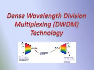
Dense Wavelength Division Multiplexing Wavelength Division Multiplexer Wavelength Division Demultiplexer Fibre l1 l1 A X l2 l2 B Y l1 + l2 + l3 l3 l3 C Z • Multiple channels of information carried over the same fibre, each using an individual wavelength • Dense WDM is WDM utilising closely spaced channels • Channel spacing reduced to 1.6 nm and less • Cost effective way of increasing capacity without replacing fibre • Commercial systems available with capacities of 32 channels and upwards; > 80 Gb/s per fibre
Simple DWDM System Wavelength Division Multiplexer Wavelength Division Demultiplexer l1 l1 Fibre T1 R1 l2 l2 T2 R2 l1 + l2 ... lN lN lN TN RN Multiple channels of information carried over the same fibre, each using an individual wavelength Unlike CWDM channels are much closer together Transmitter T1 communicates with Receiver R1 as if connected by a dedicated fibre as does T2 and R2 and so on Source: Master 7_4
Sample DWDM Signal Multiplexer Optical Output Spectrum for an 8 DWDM channel system, showing individual channels Source: Master 7_4
DWDM: Key Issues • Dense WDM is WDM utilising closely spaced channels • Channel spacing reduced to 1.6 nm and less • Cost effective way of increasing capacity without replacing fibre • Commercial systems available with capacities of 32 channels and upwards; > 80 Gb/s per fibre • Allows new optical network topologies, for example high speed metropolitian rings • Optical amplifiers are also a key component Source: Master 7_4
Terabit Transmission using DWDM • 1.1 Tbits/sec total bit rate (more than 13 million telephone channels) • 55 wavelengths at 20 Gbits/sec each • 1550 nm operation over 150 km with dispersion compensation • Bandwidth from 1531.7 nm to 1564.07 nm (0.6 nm spacing)
Capacity Expansion Options (I) • Install more fibre • New fibre is expensive to install (Euro 100k + per km) • Fibre routes require a right-of-way • Additional regenerators and/or amplifiers may be required • Install more SDH network elements over dark fibre • Additional regenerators and/or amplifiers may be required • More space needed in buildings
Capacity Expansion Options (II) • Install higher speed SDH network elements • Speeds above STM-16 not yet trivial to deploy • STM-64 price points have not yet fallen sufficiently • No visible expansion options beyond 10 Gbit/s • May require network redesign • Install DWDM • Incremental capacity expansion to 80 Gbits/s and beyond • Allows reuse of the installed equipment base
DWDM Advantages • Greater fibre capacity • Easier network expansion • No new fibre needed • Just add a new wavelength • Incremental cost for a new channel is low • No need to replace many components such as optical amplifiers • DWDM systems capable of longer span lengths • TDM approach using STM-64 is more costly and more susceptible to chromatic and polarization mode dispersion • Can move to STM-64 when economics improve
DWDM versus TDM • DWDM can give increases in capacity which TDM cannot match • Higher speed TDM systems are very expensive
DWDM Disadvantages • Not cost-effective for low channel numbers • Fixed cost of mux/demux, transponder, other system components • Introduces another element, the frequency domain, to network design and management • SONET/SDH network management systems not well equipped to handle DWDM topologies • DWDM performance monitoring and protection methodologies developing
DWDM: Commercial Issues • DWDM installed on a large scale first in the USA • larger proportion of longer >1000km links • Earlier onset of "fibre exhaust" (saturation of capacity) in 1995-96 • Market is gathering momentum in Europe • Increase in date traffic has existing operators deploying DWDM • New entrants particularly keen to use DWDM in Europe • Need a scaleable infrastructure to cope with demand as it grows • DWDM allows incremental capacity increases • DWDM is viewed as an integral part of a market entry strategy
DWDM Standards Source: Master 7_4
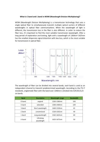
DWDM Standards • ITU Recommendation is G.692 "Optical interfaces for multichannel systems with optical amplifiers" • G.692 includes a number of DWDM channel plans • Channel separation set at: • 50, 100 and 200 GHz • equivalent to approximate wavelength spacings of 0.4, 0.8 and 1.6 nm • Channels lie in the range 1530.3 nm to 1567.1 nm (so-called C-Band) • Newer "L-Band" exists from about 1570 nm to 1620 nm • Supervisory channel also specified at 1510 nm to handle alarms and monitoring Source: Master 7_4
Optical Spectral Bands 2nd Window O Band 5th Window E Band S Band C Band L Band 1500 1400 1200 1600 1300 1700 Wavelength in nm
Channel Spacing • Trend is toward smaller channel spacings, to incease the channel count • ITU channel spacings are 0.4 nm, 0.8 nm and 1.6 nm (50, 100 and 200 GHz) • Proposed spacings of 0.2 nm (25 GHz) and even 0.1 nm (12.5 GHz) • Requires laser sources with excellent long term wavelength stability, better than 10 pm • One target is to allow more channels in the C-band without other upgrades 0.8 nm 1553 1552 1550 1553 1551 1554 Wavelength in nm
ITU DWDM Channel Plan0.4 nm Spacing (50 GHz) All Wavelengths in nm 1528.77 1529.16 1529.55 1529.94 1530.33 1530.72 1531.12 1531.51 1531.90 1532.29 1532.68 1533.07 1533.47 1533.86 1534.25 1534.64 1535.04 1535.43 1535.82 1536.22 1536.61 1537.00 1537.40 1537.79 1538.19 1538.58 1538.98 1539.37 1539.77 1540.16 1540.56 1540.95 1541.35 1541.75 1542.14 1542.54 1542.94 1543.33 1543.73 1544.13 1544.53 1544.92 1545.32 1545.72 1546.12 1546.52 1546.92 1547.32 1547.72 1548.11 1548.51 1548.91 1549.32 1549.72 1550.12 1550.52 1550.92 1551.32 1551.72 1552.12 1552.52 1552.93 1553.33 1553.73 1554.13 1554.54 1554.94 1555.34 1555.75 1556.15 1556.55 1556.96 1557.36 1557.77 1558.17 1558.58 1558.98 1559.39 1559.79 1560.20 1560.61 So called ITU C-Band 81 channels defined Another band called the L-band exists above 1565 nm Speed of Light assumed to be 2.99792458 x 10⁸ m/s
ITU DWDM Channel Plan 0.8 nm Spacing (100 GHz) All Wavelengths in nm 1534.64 1535.43 1536.22 1537.00 1537.79 1538.58 1539.37 1540.16 1528.77 1529.55 1530.33 1531.12 1531.90 1532.68 1533.47 1534.25 1540.56 1541.35 1542.14 1542.94 1543.73 1544.53 1545.32 1546.12 1546.52 1547.32 1548.11 1548.91 1549.72 1550.52 1551.32 1552.12 1552.52 1553.33 1554.13 1554.94 1555.75 1556.55 1557.36 1558.17 1558.98 1559.79 1560.61 Speed of Light assumed to be 2.99792458 x 10⁸ m/s
DWDM System Receivers DWDM Multiplexer Optical fibre Power Amp Line Amp Line Amp Receive Preamp DWDM DeMultiplexer Transmitters 200 km • Each wavelength behaves as if it has it own "virtual fibre" • Optical amplifiers needed to overcome losses in mux/demux and long fibre spans
Receivers DWDM Multiplexer Optical fibre Power Amp Line Amp Line Amp Receive Preamp DWDM DeMultiplexer Transmitters
DWDM: Typical Components • Passive Components: • Gain equalisation filter for fibre amplifiers • Bragg gratings based demultiplexer • Array Waveguide multiplexers/demultiplexers • Add/Drop Coupler • Active Components/Subsystems: • Transceivers and Transponders • DFB lasers at ITU specified wavelengths • DWDM flat Erbium Fibre amplifiers
Constructive Interference l A + B A nl + l S Source nl B • Travelling on two different paths, both waves recombine (at the summer, S) • Because of the l path length difference the waves are in-phase • Complete reinforcement occurs, so-called constructive interference
Destructive Interference l A A + B nl + 0.5 l S Source nl B • Travelling on two different paths, both waves recombine (at the summer, S) • Because of the 0.5l path length difference the waves are out of phase • Complete cancellation occurs, so-called destructive interference
Using Interference to Select a Wavelength A + B A nl + Dl S Source nl B • Two different wavelengths, both travelling on two different paths • Because of the path length difference the "Red" wavelength undergoes constructive interference while the "Green" suffers destructive interference • Only the Red wavelength is selected, Green is rejected
Array Waveguide Grating Operation: Demultiplexing Constant path difference = DL between waveguides l1 .... l5 Waveguides Coupler Input fibre All of the wavelengths l1 .... l5 travel along all of the waveguides. But because of the constant path difference between the waveguides a given wavelength emerges in phase only at the input to ONE output fibre. At all other output fibres destructive interference cancels out that wavelength. l5 l1 Output fibres
Array Waveguide Operation • An Array Waveguide Demux consists of three parts : • 1st star coupler, • Arrayed waveguide grating with the constant path length difference • 2nd star coupler. • The input light radiates in the 1st star coupler and then propagates through the arrayed waveguides which act as the discrete phase shifter. • In the 2nd star coupler, light beams converges into various focal positions according to the wavelength. • Low loss, typically 6 dB
DWDM System Receivers DWDM Multiplexer Optical fibre Power Amp Line Amp Line Amp Receive Preamp DWDM DeMultiplexer Transmitters 200 km • Each wavelength behaves as if it has it own "virtual fibre" • Optical amplifiers needed to overcome losses in mux/demux andlong fibre spans
DWDM System with Add-Drop Add/Drop Mux/Demux Receivers DWDM Multiplexer Optical fibre Receive Preamp Power Amp Line Amp DWDM DeMultiplexer Transmitters 200 km • Each wavelength still behaves as if it has it own "virtual fibre" • Wavelengths can be added and dropped as required at some intermediate location