ATDI Propagation Models in ICS telecom
670 likes | 1.79k Vues
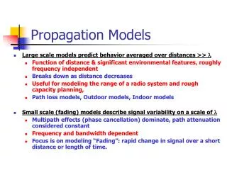
ATDI Propagation Models in ICS telecom. Webinar aim: identify which radio propagation models are implemented in ICS telecom Including: Propagation model limitations Clutter settings What calculations take place Identifying the most appropriate model

ATDI Propagation Models in ICS telecom
E N D
Presentation Transcript
Webinar aim: identify which radio propagation models are implemented in ICS telecom Including: • Propagation model limitations • Clutter settings • What calculations take place • Identifying the most appropriate model • Examining the useful / popular radio propagation models nb.Due to time constraints the lesser known radio propagation models including corrections such as rain, gas and reflections will not be covered.
Webinar aim: present propagation models in a similar form to ITU-R P.1144-5 A guide to radio propagation models in ICS telecom will be published shortly.
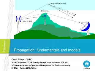
Definitions • Digital Terrain Model (DTM) – bare ground height – man-made modifications tend to be ignored such as cuttings and embankments, etc • Clutter – What is on the bare ground including trees, buildings (suburban, urban) • Absorption • Diffraction • T = transmitter • R = receiver Power absorbed by obstacle Diffraction loss
How clutter is used Clutter code 9 Used for “building layers” – not covered in this presentation Applies factor to clutter height ie, if forrest15m high diffraction point = 0.6 x 15 = 9m Clutter height Applied at all locations dB/km applied every time clutter is in transit Flat attenuation Applied only at Receiver pixel
Clutter settings Clutter T/R over ground spot RX Over Clutter Clutter T/R over ground relaxed Over Ground RX Ground
General Concept Represents pixel of ground (DTM) Represents pixel of clutter urban
Represents pixel of ground (DTM) Represents pixel of clutter suburban Represents pixel of clutter urban
Diffraction loss From last diffraction point dB/km Represents pixel on ground (DTM) Represents pixel of clutter urban with clutter height x and dB/km y Absorption loss = 4 x y / DTM raster size Clutter attenuation = MIN (diffraction loss , absorption loss) Clutter attenuation = Diffraction loss + Absorption loss
Diffraction loss from last diffraction point A B Flat attenuation Absorption loss = 4 x y / DTM raster size At Location A (RX height > Clutter height) Clutter attenuation = MIN(Diffraction loss , Absorption loss) Clutter attenuation = Diffraction loss + Absorption loss At Location B (RX height < Clutter height) Clutter attenuation = MIN(Diffraction loss , Absorption loss) + Flat attenuation Clutter attenuation = Diffraction loss + Absorption loss + Flat attenuation
Diffraction loss from last diffraction point Flat + absorption 10dB 10dB Represents pixel of ground (DTM) Represents pixel of clutter urban with clutter height x and dB/km y Clutter attenuation = MIN (Diffraction loss , Absorption loss = summation of flat loss for each separate obstacle) Clutter attenuation = Diffraction loss + Absorption loss which is summation of flat loss for Each separate obstacle
Clutter height 8m Clutter height 30m 10dB
Diffraction loss Only if RX > clutter height Flat + diffraction mode If RX height < Clutter height Clutter loss = diffraction + clutter attenuations into RX pixel)
Clutter not used in calculation Clutter when using DSM or DEM Clutter might be used to identify Roof tops / street levels
Other Clutter modes • CCIR and UER are similar to flat + diffraction, except with standard values for mobiles (CCIR) and TV reception (UER) • TSB-88 Mode (NTIA report TSB-88-B similar to flat + diffraction except clutter attenuation need to change with frequency (clutter height should be set to zero) • USER same as flat + diffraction except where RX height > clutter height in which case it is diffraction + flat attenuation into last pixel Clutter code 9 has a specific role and is used as identification for building layer Building layers are not covered in this webinar Demonstrate best way to test clutter settings and attenuations. DEMO
Radio Propagation Models • Main Models • ITU-R 525/526 Deygout • ITU-R 525/526 Bullington • ITU-R 1546-3 • ITU-R 1812-2 • ITU-R 452 • Other Useful Models • Okumura/ Hata / Davids • ITU-R 528 (optional add on) These models will be covered in detail during this webinar.
These models will not be covered during the webinar . The applicability of these models will be covered in the Guide to Radio Propagation models • Other models • Fresnel method + • Wojnar method • Wein method • ITU-R 370 • ITU-R 1225 • Medium Frequency • 3GPP – LTE Rural • 3GPP – LTE urban • SUI method • Hata – Cost 231 • Cost 231 Open • SkywaveLF & MF • Add-on models • Itm122 - Irregular Terrain Model • ITM_NTIA Longley Rice (ITM) • Ground wave – ITU-R P368-7 • RRC04 • Skywave ITU-R P.435, ITU-R P.1147 • Tropospheric Scatter
ICS Telecom / HTZ Warfare Radio Propagation model settings Some propagation models do not split into these 3 conditions easily; in some cases they do not apply • In concept TX Location RX Location(s)
ITU-R 525 / 526 Deygout • Standard model in ICS telecom since version 1 • Three worst-case intrusions into the Fresnel zone taken into account • ATDI updated method with Deygout94 diffraction wheremultiple intrusions are taken into account • The ITU have now updated method
ITU-R 525/526-12 Bullington • 526 model uses the following parts of 526-12 • Spherical earth section 3.2 • Bullington model section 4.5 • Rounded earth, knife edge, multiple obstacles , smooth earth not implemented because it causes discontinuities as models switch Bullington model uses single effective Diffraction point
ITU-R 452 • Point to Point calculation • Based on ITU-R P. 525 / 526-10 (Deygout)** • For 50 to 0.001% time • Settings must be correct in ICS telecom • 2 clutter variables in the calculation ha and dk. • - ha is set in clutter heights • dk value applied is based on clutter code ** Note this will be changed to Bullington in near future
The codes 2,3,4,5,8,10 are fixed for a given clutter • e.g. if you have coniferous trees it must be code 8 , then fill in height = 20m. • Similarly, .dkis derived from a lookup – DON’T enter it. • If clutter code=8 (Coniferous trees), dk=0.05; • If clutter code=5 (Tropical rain forest), dk=0.03; • If clutter code=2, 3 or 4 (Urban), dk=0.02; • If clutter code=10 (Industrial zone), dk=0.05. • For the remaining clutters, fill in the heights and it will use the corresponding value of dk: • If clutter height=4m, dk=0.1; • If clutter height=5m, dk=0.07; • If clutter height=15m, dk=0.05; • If clutter height=9m, dk=0.025; • If clutter height=12m, dk=0.02; • If clutter height=25m, dk=0.02; • ha must be set in the clutter dialogue box
MUST be un-ticked ITU-R P.453 (Fig 1,2) or 452-14 (Fig 13) ITU-R P.453 (Fig 4-7) or P. 452-14 (Fig 11) Recommended clutter settings based on 452-14 Table 4 ATDI recommends that ATDI standard clutter designations are used Note 1: Clutter level 6 must be sea / water Note 2: Ofcom has modified version of Infotera Clutter to use with P.452 model.
ITU-R 1546 • Broadcast / International Coordination / Interference • Related to ITU-R 370 • Only considers terrain within 15km of transmitter • Uses clutter and takes off angle to modify prediction • Uses propagation curves for different frequencies / % time • Not symmetrical (loss A B Loss B A ) If not standard then ATDI clutter codes will need to be set up
ITU-R 1812-2 • This is a combination of ITU-R P.452, P525, P526-12 and is for point to area calculations • This is the only propagation model that takes clutter into account at both ends of the path
ITU-R P.1812-2 Terminal clutter height is related to Clutter code (ITU-R P.1812-2 Table 2) ATDI Clutter code 6 0 1 2,3,4,5,8 7
Okumura Hata • Mobile operators tend to use this model and fine tune it with drive tests • Model is based on clutter not terrain, so is designed for small ranges The extended Hata model has not been implemented yet. If required please let ATDI know. NB. this model is for SRD with ranges in meters and for indoor and outdoor. To use this model effectively on a DTM a high resolution map would be required (1 -5 m / pixel)
Loss Distance Propagation Regions Note: This propagation model is an add on to ICS Telecom and needs to be Purchased separately
Other Corrections to Propagation Models • Rain - World based on ITU-R P.538 and UK rain on Ofcom data • Snow – Isotherm level (level at which water freezes) if path passes though this level this correction is applied • Fog – ITU-R 840 • Gas – ITU-R 676 (Note ITU-R F.1820 is Gas attenuation from HAP at 47GHz) • Wave height - (applies an effective clutter height depending on wind strength) • Reflections
Thank you for attending todayAny questions?ATDI LimitedThe Beehive – City Place – GatwickWest Sussex – RH6 0PA – UKTel +44 (0)1293 522052 - Fax +44 (0)1293 522521Email: sales@atdi.co.uk