Download
1 / 30
300 likes | 414 Vues
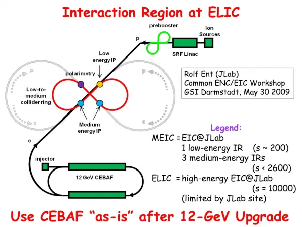
Interaction Region of PEP-II. M. Sullivan for the ILC MDI workshop January 6-8, 2005. Initial IR design parameters Initial beam parameters Detector constraints IR design Present performance and issues New beam parameters Luminosity background Summary. Outline. SLAC beam lines.

E N D
Interaction Region of PEP-II M. Sullivan for the ILC MDI workshop January 6-8, 2005
Initial IR design parameters • Initial beam parameters • Detector constraints • IR design • Present performance and issues • New beam parameters • Luminosity background • Summary Outline
Energy asymmetry of 9 on 3.1 GeV Head-on collision Bunch separation of 1.26 m 25 mm separation between BSC envelopes at 2.8 m (room for a septum magnet) SR masking No direct hits on the detector beam pipe No surfaces that can one bounce to the detector beam pipe This leaves mask tip scattering as the dominate SR source Initial IR Design Parameters
Collision Frequency 238 MHz Number of bunches 1650 Bunch spacing 1.26 m Charge/bunch (L/H) 5.9x10¹⁰ 2.1x10¹⁰ IP Beta X,Y 0.50, 0.015 m Emittance X, Y 48, 1.5 nm-rad Bunch size (x, y, z) 155, 4.7, 10000 µm Currents (L/H) 2.1 A 0.75 A Luminosity 3x1033 cm-2 sec-1 Initial Beam Parameters
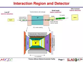
Detector acceptance minimum angle of 300 mrad Detector magnetic field of 1.5T Minimum thickness beam pipe 4 µm Au 800 µm Be 1 mm water 400 µm Be Detector center shifted in Z +0.37 m Detector Constraints
Present status • We have achieved y*s of 10 mm • With x*s of 30 cm • Bunch lengths are estimated to be 11-13 mm • Total beam currents of 2.450 A on 1.550 A (1.590 on 2.540 on last shift) • No sign of SR backgrounds • Fairly large luminosity background • Total current in the support tube up to 4.1 A! • Heating in the IR support tube (from Q2 to Q2) OK so far • NEG pump heating by HOM power
IR Be bellows NEG pumps in the LER Q1/Q2 bellows Bellows in region 4 Bellows in region 10 Past and Present HOM heating
SS sleeves Bellows Detail Al heat sink Cu pipe Be is coated with about 4 mm of Au RF shield Be to SS braze Transverse H11 mode can couple through the RF shield
350 °F LER NEG Pump Temperatures Lab test data of NEG outgassing as a function of temperature Upstream LER side
Collision Frequency 238 MHz Number of bunches1710 Bunch spacing 1.26 m Charge/bunch (L/H)12.6x10103.5x1010 IP Beta X,Y0.30, 0.008m Emittance X, Y60, 1.0 nm-rad Spot size (x, y, z)134, 2.8, 9000 µm Currents (L/H)4.5 A 2.2 A Luminosity 2x1034 cm-2 sec-1 New Beam Parameters
Issues for the near future • Run 5 goals that affect the IR • LER current of 3.3 A • HER current of 1.8 A • Higher bunch currents more HOM power • Shorter LER bunch length more HOM power • Lower y*s to 9 mm • Lower LER x* to 30 cm • Increase LER emittance to 50 nmrad Total of 5.1 A ! BSCs
Issues for the farther future • Ultimate goals that affect the IR • LER current of 4.5 A • HER current of 2.2 A • Still higher bunch currents more HOM power • Still shorter bunch lengths more HOM power • Lower y*s to 8 mm • Lower LER x* to 30 cm • Increase LER emittance to 60 nmrad Total of 6.7 A !! BSCs
BSCs Plenty of room on the backward side Present machine parameters LER x*= 30 cm and LER x = 22 nmrad LER x* may be a little low, but it is the value for run 5 BSC just clears the present Q2 chamber on the forward side
BSCs Just enough room for the beam Expected LER beam size for run 5 LER parameters: x* = 30 cm x = 50 nmrad BSC is defined as 15 + 2mm (uncoupled) BSC violated at the septum New chamber being built and RFI by April or May
Luminosity versus CrossingAngle Without parasitic crossing With parasitic crossing
Comparisons between stronger B1s, crossing angles and energy changes • The parasitic crossing separations are: • Present design 3.22 mm • 30% Stronger B1 (Nd) 3.6-3.8 mm (12-17%) • Stronger B1 (volume) 3.5-3.9 mm (9-21%) • With +/- 0.5 mrad x angle 3.9-4.0 mm (21-24%) • The energy differences for the crossing angle option are: • HER 8.9732 to 8.7450 (-2.5%) • LER 3.1186 to 3.2000 (+2.6%) • Increase the energy asymmetry AND remove last B1 slice • Very preliminary look with head-on collisions: • HER energy 8.9732 9.427 GeV +5.1% and • LER energy 3.1186 2.969 GeV - 4.8% PC separation of 3.55 mm (10%)
Detector Backgrounds in the Future • Synchrotron radiation masking has been checked OK with a 7mm beta y* • Local beam-gas and coulomb should be essentially unchanged since the geometry is almost the same and the masking is the same. These backgrounds should slowly improve as the total number of A-hrs increases • Radiative Bhabhas as a background that increases as the luminosity increases
Summary • The PEP-II interaction region has performed very well • The PEP-II accelerator is starting to move into a new area of performance where HOM power will play a much larger role. The higher beam currents and higher bunch currents contribute to the higher HOM power as well as to higher SR power. • So far we have addressed two major issues in the IR concerning HOM heating – Be bellows heating and NEG pump heating. Other regions will bear watching as well as other vacuum components. • The IR upgrade is looking at modifying the B1 bending magnets to improve the beam separation at the 1st parasitic crossing while maintaining head-on collisions. Stronger magnetic material is needed to do this. However, we have not found a material that is comfortably rad-hard. • The option of adding a small crossing angle (+/- 0.5 mrad) using the present hardware can be done by changing the beam energies by about +/- 2.5%. • Detector backgrounds that are a function of the luminosity will become more important as the luminosity increases