Motivation
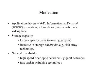
Motivation. IC business requires a sub 100 nm Next Generation Lithography tool. (100 nm for 16GDRAM) Any of the following 4 major candidates are not prevailing. EUV(Extreme UV) SCALPEL(SCattering with Angular Limitation in Projection Electron beam Lithography) X-ray with Synchrotron

Motivation
E N D
Presentation Transcript
Motivation • IC business requires a sub 100 nm Next Generation Lithography tool. • (100 nm for 16GDRAM) • Any of the following 4 major candidates are not prevailing. • EUV(Extreme UV) • SCALPEL(SCattering with Angular Limitation in Projection Electron beam Lithography) • X-ray with Synchrotron • IPL(Ion Projection Lithography) • Generally, it is assumed that due to the large lateral straggling of ions in the membrane mask, it is not possible to get high resolution with ion beam - which is not necessarily so. • As a first step towards Ion beam lithography (IBL) using membrane mask, it is necessary to demonstrate the good spatial resolution
Advantage and Disadvantage of IBL Advantage • Good sensitivity for 0.1 um pattern • X-ray : 375 mJ/cm2 • e-beam : 100 uC/cm2 • IBL : 4.5 uC/cm2 (720mJ) • Good intrinsic resolution • 10 nm : limitation not from the wavelength but from PR Disadvantage • vacuum treatment • 1:1 membrane mask • lateral straggling • non familiar method - no extensive study
Current Status of Ion Beam Lithography IPL • IMS (Ionen Mikrofabikations System) and Vienna University since 1986 • ALG consortium in USA • Siemens, ASM lithography, Leica and IMS-Stuttgart formulated $36M 3-year research program in 2000 • 0.1 um pre-production type stepper in 1999 IBL with membrane mask • No dominant study after the proximity IBL by Hughes Research Laboratory
Simulation of Dose distribution at PR • Purpose : To see and understand the dose distribution at pattern edges which is directly responsible for the edge definition in the development process • Simulation tool : TRIM (SRIM2000) • Simulation Geometry : simple infinite slit
Ion Beam quality Parellelity and homogeniety dose measurement Mask Quality mask production by e-beam writer problem : approx. 1 mm thick PMMA should be used - Resolution worsening distortion during irradiation Factors affecting the line definition Development • precise temperature control - find the temperature at which until the midde irradiated point is developed • not controllable by develop time because of the statistical character of melting process
Change of molecular weight by proton irradiation • Molecular weight of PMMA changes drastically by proton irradiation which enables the very well defined structure reproduction
Result of simulation - 1mm slit Small conclusion • Theoretically, the edge definition can be controlled within 20 nm if the development process can be performed very precisely • Even taking into account the 14 - 86 % dose width, edge definition can be controlled at least within 50nm with rather rough develop condition
Comparison of Simulation and Experiment- for the case of large mask to PR distance Depth profile of PMMA after development Proton Energy : 500keV Membrane : 2mm Si3N4 shadow width : 100mm Mask to PR distance : 35mm
Extreme Cases Depth profile of PMMA after development Proton Energy : 500keV Membrane : 2mm Si3N4 shadow width : 100mm Mask to PR distance = 0 Mask to PR distance = 530mm
AFM results Edge configuration 500keV proton Au wire mask w/o membrane Edge configuration 800 keV proton Au wire mask with 10 mm mylar membrane
SEM observations 400keV with membrane mask to sample : contact tilt angle 50o 500keV w/o membrane tilt angle 50o 450keV with membrane mask to sample : 25mm tilt angle 50o
Conclusion • Simulation results show the good possibility of employing IBL using membrane mask as the NGL tool. • Well below 100nm pattern definition can be obtained if develop condition can be found at which only until the middle dose position at the pattern edge is developed. • There are still, however, many basic works to be performed before real launch. They are : 1. The relationship between proton dose, develop condition (Temperature, time) and pattern edge (the position until which PR is developed) 2. Mask quality (e-beam writing) 3. Understanding the deviation of simulation result and the real measurement
수백 keV 양성자를 이용한 이온빔 리소그라피의 분해능 측정 김영석, 홍완, 우형주, 최한우 한국자원연구소 이온빔응용연구그룹