
Using Diagrams to Represent Program Structure
E N D
Presentation Transcript
Using Diagrams to Represent Program Structure OMT and UML Some pictures and material are from “Design Patterns” by Gamma et al
Outline • why diagrams • diagram types • class diagram elements • class • aggregation • inheritance • instantiation • class diagram examples • object diagram • use case diagram • interaction diagram
Why Diagrams • diagrams is a way to capture the essential aspects of the program • have an overview of the whole program • see the important relationships between elements of program • get the picture of the program before it is coded • standardized as part of • object modeling technique (OMT) – Rumbaugh, Blaha, et al 1991 • universal modeling language (UML) – Rational Rose Inc. and other companies • used in program planning, development and documentation • language independent (not necessarily C++)
Diagram Types • structure diagram – emphasizes what constructs must be present in the modeled system • class diagram – the system classes, attributes, their relationships • object diagram – a view of the modeled system at a specific execution instance • behavior diagram – emphasizes what actions must happen in the system • use-case diagram – system functionality in terms of interaction with outside actors • interaction diagram – flow of control and data among constructs
Classes class Example{ public: void showchar(); string getstring(); private: char c; string str; }; • operations – member functions/methods • instance variables – member variables/attributes ClassName Example instVar1: TypeinstVar2: Type c: charstr: string oper2(): returnType oper1(argName: argType): rType showchar(): voidgetstring(): string class BankAccount{ public: void deposit(dollars amount); void withdrawal(dollars amount); private: string owner; dollars balance; };
Aggregation • if class contains instances (objects) of other classes the class aggregates them • if class aggregates more than one instance of the same class it is shown diagramatically • multiplicity - shows how many instances of objects on each side
Inheritance, Reference and Instantiation Class inheritance • class contains a reference to another Additional comments • object creation (class instantiation) is done by a method of another class
Example Class Diagram 3 • blah
Object Diagram • shows objects and references as the program is executed • what would be a class and an object diagram for an object with dynamically allocated members?
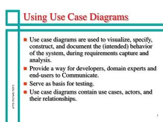
Use Case Diagrams • written description of the system’s behavior regarding tasks or requirements • captures interactions between actors (outside entities) and the system through use cases use case actor
Interaction (Sequence) Diagram • shows order in which requests (methods) between objects are executed - scenario, typically within a single use case • boxes – processes (function invocation) in each object • lines – messages (interaction) between objects
Questions on Diagrams • What is the purpose for the use of diagrams • What is the difference between structure and behavior diagrams? • What types of structure diagrams we have studied? Behavior diagrams? • How is class denoted on a structure diagram? • What is aggregator/agregatee? How is their relationship denoted? • What is multiplicity and how is it denoted? • How are objects denoted on an a structure diagram? • What diagram uses use cases, actors? What is system boundary? • What do boxes and lines and crosses represent in a flow diagram?