Download
1 / 33
470 likes | 1.59k Vues
Shell & Tube Heat Exchanger (STHE) Overpressure Protection from Tube Rupture . Colin Deddis, BP Exploration Operating Co Ltd 19 July 2011. STHE Overpressure Protection Acknowledgements. Ian Wyatt, Atkins Ltd Stephen Murray, Health and Safety Executive Bruce Ewan, University of Sheffield

E N D
Shell & Tube Heat Exchanger (STHE) Overpressure Protectionfrom Tube Rupture Colin Deddis, BP Exploration Operating Co Ltd 19 July 2011
STHE Overpressure ProtectionAcknowledgements Ian Wyatt, Atkins Ltd Stephen Murray, Health and Safety Executive Bruce Ewan, University of Sheffield Colin Weil, Consultant Mark Scanlon, Energy Institute
STHE Overpressure Protection • Tube rupture scenario • Guidance & practice – changes since 2000 • Dynamic analysis of STHE overpressure and relief • Current industry design practices • Design & operational issues with bursting disks in this service • Energy Institute JIP Proposal
Different Exchanger Configurations Similar Tube Rupture consequences apply to all of these configurations: • Single pass gas, single pass liquid • Multiple pass gas and/or multiple pass liquid • HP Gas on tube side or shell side • Cooling Duty or Heating Duty • Horizontal or Vertical or Angled
Stages to Tube Rupture For all configurations there are four phases to the consequences of a Tube Rupture – identified in the tube rupture tests performed as part of the previous JIP by the Institute of Petroleum: Phase I – Percussive Shock Phase II – Fast Transient Phase III – Liquid Discharge Phase IV – Gas Discharge
Phase I – Percussive Shock • Rapid rupture creates percussive shock wave • Extremely short lived <0.1ms • Shell does not ‘feel’ the pressure spikes • Not Modelled
Phase II – Fast Transient • Gas entering shell is faster than time to overcome liquid momentum • Fast transient pressure wave results travelling at sonic velocity • Pressure wave usually breaks bursting disc • Shell and pipework overpressures possible • Simulated using software with necessary fast transient capability • Shell baffle path ‘straightened’ – 1D Model
Phase III – Liquid Discharge • Gas bubble grows towards exits • Liquid displaced through available exits • Volume flow balance between bubble and displaced liquid • Possible to over pressurise Shell and connected pipework • Gas-Liquid interfaces affect pipe supports • Shell baffle path ‘straightened’ – 1D Model
Phase IV – Gas Discharge • Gas from rupture passes out of system • Pseudo steady state depending on gas supply • Usually not modelled
Changes in Industry Guidance (API521/BS EN ISO 23251) • Two-thirds rule replaced with: • “Loss of containment of the low-pressure side to atmosphere is unlikely to result from a tube rupture where the pressure in the low-pressure side (including upstream and downstream systems) during the tube rupture does not exceed the corrected hydrotest pressure” • “Pressure relief for tube rupture is not required where the low-pressure exchanger side (including upstream and downstream systems) does not exceed the criteria noted above.” • Dynamic analysis added: • “This type of analysis is recommended, in addition to the steady-state approach, where there is a wide difference in design pressure between the two exchanger sides [e.g. 7 000 kPa (approx. 1 000 psi) or more], especially where the low-pressure side is liquid-full and the high-pressure side contains a gas or a fluid that flashes across the rupture. Modelling has shown that, under these circumstances, transient conditions can produce overpressure above the test pressure, even when protected by a pressure-relief device [64], [65], [66]. In these cases, additional protection measures should be considered.”
Changes in Industry Guidance (API521/BS EN ISO 23251) • Tube rupture design basis added: • “The user may perform a detailed analysis and/or appropriately design the heat exchanger to determine the design basis other than a full-bore tube rupture. However, each exchanger type should be evaluated for a small tube leak. The detailed analysis should consider a) tube vibration, b) tube material, c) tube wall thickness, d) tube erosion, e) brittle fracture potential, f) fatigue or creep, g) corrosion or degradation of tubes and tubesheets, h) tube inspection programme, i) tube to baffle chafing.”
Current Industry Design Practice • API521/BS EN ISO 23251 allows use of relief valves or bursting disks but states: • “The opening time for the device used…..should also be compatible with the requirements of the system.” • Opening times of relief valves considered to be too slow, hence bursting disks commonly used. • Advances in heat exchanger design practice e.g. vibration analysis, materials selection etc.
Example of Pressure Transients in Shell(HP gas at 180 barg in tubes; cooling water at 5.4 barg; PSV opening in 50 msecs) Peak pressures due to reflected waves Pressure in shell local to break at tubesheet Phase 3 Phase 2 Shell design pressure = 14 barg Tube rupture occurs at 0.01 s
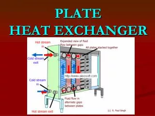
“Typical” HP/LP shell & tube heat exchanger design(compressor recycle cooler for offshore service) Relief to flare (designed for slug flow) Shutdown valve Gas inlet Bursting disks in parallel Water outlet Segmental baffles (no tube in window) Water inlet Gas outlet Possible shutdown valve Check valve Adapted from IP Guidelines for the Design and Sae Operation of Shell & Tube Heat Exchangers to Withstand the Impact of Tube Failure, Aug 2000
STHE Overpressure Protection • Increased use of bursting disks to protect STHEs over past 10 to 15 years • Estimated frequency of tube failure • 0.0009 per unit per year (~1 per 1,100 years)[1] • Frequency of bursting disk failures protecting STHEs • 7 incidents in 13 years (~50 exchangers) • 0.011 per unit per year (~1 per 90 years)[2] • Future growth in numbers of high pressure STHEs requiring overpressure protection • IP Guidelines for the Design and Sae Operation of Shell & Tube Heat Exchangers to Withstand the Impact of Tube Failure, Aug 2000 • Estimate based on incidents in upstream oil and gas industry known to BP
STHE Overpressure Protection Two major hazards associated with bursting disk failures: • Impairment of relief system – liquid inflow & overfill • Incident escalation - reverse rupture may lead to uncontrolled hydrocarbon release from relief system
Flare Relief Header PSHH Flare Knockout Drum Incident #1 – liquid overfill • Bursting disk rupture in forward direction • PSHH in void space of bursting disk assembly fails to isolate exchanger • Sustained cooling medium flow into relief system • Liquid overfill & potential overpressure of knockout drum
Bursting disc failure: flare system impairment Stephen Murray HSE Inspector, Offshore Division
HSE Safety Alert 01/2008 Summary • uncontrolled flow of seawater into flare system • several hours to identify source • flaring event may have lead to serious gas release
HSE Safety Alert 01/2008 Lessons • Be aware of potential for impairment of flare/relief system from uncontrolled cooling medium flow from ruptured bursting disc • Ensure disc rupture will initiate measures to ensure isolation of cooling medium so that flare/relief system is not compromised
Hazard #2 – excessive backpressure 80 psig backpressure 50 psig 100 psig 225 psig 225 psig
Design & Operational Issues • Bursting disks when utilised for overpressure protection of STHEs • Once opened, they maintain an open flow path from the process/utility system to the relief system. • A sufficient margin (~30%) needs to be maintained between operating and set pressure to avoid opening in absence of a tube failure. In STHE applications, they are often located on cooling medium systems which can be susceptible to pressure surges. • Failure in the reverse direction due to superimposed backpressures from the relief system.
Design Requirements • Selection of relief route should consider: • Multiphase – high velocity liquid slugs • HP or LP flare system (high pressure gas under relief conditions but large liquid volumes under a failure case) • segregation from other relief routes to avoid mitigate reverse rupture • HAZOP required to identify potential failure modes and consequences. • Additional detection and safeguards required for failure cases.
Gaps in current industry guidance • Broader design requirements associated with bursting disks and interface with relief systems not addressed • No industry guidance on a pressure ratio at which relief valves are acceptable • Large differential pressure may actually favour relief valve – extent of overpressure may yield sufficiently rapid response • Lower differential pressures – shell & nozzles may survive overpressure. • No acceptance criteria available for short duration transient overpressures
Aims of Energy Institute JIP • Eliminate or mitigate hazards associated with overpressure protection of STHEs • Develop revised set of design guidelines for overpressure protection of STHEs principally to address: • Heat exchanger design. • Relief device selection.
Possible Scope of Energy Institute JIP Heat Exchanger Design (1) • Determine criteria to assess if guillotine fracture is possible based on the mechanical properties of the materials of construction used in heat exchanger tubes. • Determine any minimum tube thickness specification required to prevent guillotine fracture. • Define the vibration analysis requirements that need to be applied to ensure that the likelihood of guillotine fracture is minimised. • Define any sensitivity analysis of process variations which should be carried out to ensure that the design is robust.
Possible Scope of Energy Institute JIP Heat Exchanger Design (2) • Determine if differential pressure limits can be established below which transient effects can be ignored. • Determine the maximum allowable transient overpressures in the shell under tube rupture conditions to cater for peak pressures. This will require experimental and analytical work. • Determine the impact of transient loads on the piping systems if bursting disks are not applied for overpressure and develop appropriate design guidelines to ensure that the piping design is robust but not overly conservative.
Possible Scope of Energy Institute JIP Relief Device Selection • Develop a rule-set for relief device selection to accommodate the tube rupture case • Scale-up to typical relief device sizes encountered in real applications. • Testing of response times of a variety of relief valves to a range of overpressures . • Establish mechanical integrity criteria for relief valves for use in tube rupture service. • Establish the range of process conditions for which conventional relief valves could be utilised to protect against tube rupture and those for which bursting disks are required. This needs to consider aspects such as differential design pressure between low and high pressure side of exchanger etc.
JIP Proposal Summary • Total cost estimate ~£330k • Fee structure • £30k – operating companies and safety regulators • £15k - other participants (design houses, consultancies etc.) • in-kind support from relief valve manufacturers, software providers etc. • 18 months commencing 3Q2011
Energy Institute JIP Next Steps • Details on EI website: • www.energyinst.org/sthe • Kick off meeting 19 July 2011, Energy Institute, London